

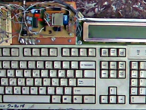
Photos
DISCLAIMER
I can not be held responsible for any damage, either to yourself, others or equipment by anyone reading this document and then trying to replicate my efforts.
ACKNOWLEDGEMENT
Let me state that this project would have taken considerably longer with dubious end results if it were not for the gifted fans out there who selfishlessly supply the freeware libraries for everyone to use. Thank you all :-)
FEATURES
-
Based on the ATMEGA644-20PU with 64KB flash, 4KB SRAM and 2KB EEPROM.
-
LCD character display 4 lines by 40 columns with linebars
-
create up to 8 custom characters for user graphics
-
support for interactive and batch modes
-
full screen line editor
-
if-else
conditional, do-while and for-next loops plus goto and gosub
statements for branching
-
compute Convolution and DFT of sequences as well as system Transfer Functions plus any combination of arithmetic and mathematical expressions in RPN
-
User defined mathematical functions
-
run interactively commands while a program is running
-
run mini loops/programs from the command line
-
execute periodically commands
-
system variables allow for timed events, average, rms, min and max values from analog pins, etc
-
104 bytes of different types of user variables that share memory among them to interact with system variables and commands allowing for bytes, short and long integers as well as floating point numbers
-
up to 1000 bytes of dynamic memory to work with ranging from unsigned chars to floating point numbers
ability to modify program data and code on the fly
-
mini oscilloscope application 16x20 dots and 50KB/sec sampling rate
-
low frequency logic capture - 3200 samples in 10.8 msec
-
slow and fast GPIO ( ~1KB/sec and >500KB/sec)
-
save/load programs and data to/from SD card, EEPROM and PC
-
autoexec to load and run a program from EEPROM after each reset
-
up to 23 GPIO pins (SPI included but no SD, no RS232)
- BUZZER for sound effects
HARDWARE
The schematic for the development board is shown below. The available pins left on the MCU were connected to female pinheaders so as to facilitate the wiring to breadboard and further experimentation. The hardware serial library has a problem with SIGNAL and the read function is problematic. I used IDE 1.0.4 since 00xx versions were incompatible with several library calls and had a flood of compiler errors. Replacing SIGNAL with ISR calls did not help as there were again library incompatibilities with some classes. Instead, the altsoftserial library (D13,D14) is used for the occasional interaction with a PC via RS232. The hardware UART pair is used by the bootloader to burn firmware. Both pairs of pins are available for GPIO when not used for serial IO. The SEIKO display is an ancient 90s model that was lying unused in my neglected and wretched lab. Modifying the code to run on smaller displays involves, mostly, altering the lcdupdate() internal function.
The appendix shows the circuit used to interface to an SD card. Thanks to www.roland-riegel.de and his useful library I extracted and modified the raw part of it to allocate dynamically the data buffer and thus save RAM and also to include support for the atmega644.
COMMANDS
All arguments/operators must be separated by at least a single space character and their order is important. Program statements start with a 2-digit number 00,...,99 followed by at least a space. These 3 first characters are mandatory and their position is fixed. Following that can be any valid statement or expression for execution. However, any text can be inserted provided there is no execution of the program. All commands and arguments are parsed by strtok as strings which means that most arguments can be variables instead of constants - where appropriate - and spaces are not critical. There is limited support for strings (double quotes) and string words (single quotes). So printing a message like 'pr “Hello World' will produce the appropriate output only if modified in a single word, such as, 'pr “HelloWorld'. There is an minor bug that renders the cursor invisible whenever output is on the 3rd and 4th lines. Simply press ESC to make it reappear (also ‘cl’).
Multiple statements can be entered on the same line and separated by a semicolon (;) - no white space needed. The following commands can not be part of a multiple statement construct: {if,else,fr,nx,do,wh,en}.
There is an autoexec-like-feature that allows the user to load a program and run it automatically after each reset. Depending on the value at EEPROM address 0 the unit will either load and run program ‘start’ (EEPROM(0)==1) or simply wait for keyboard input.
Summary of Commands & Expressions
“ : a nonprintable comment line
{} : expression evaluated
00-99 : a two digit number by itself is equivalent to goto
ai : attach interrupt 0,1,2
anfo: display the average, r.m.s, max. and min. of axxx
apl : plot the contents of axx using bar graph
ar : analog read
aw : ‘analog write’ per sanguino or more properly pwm
ca : analog capture in an array
cc : create custom characters
cl : clears the display
cmd: execute the contents of pointer p or a
cmno: find a line number index in *Prgm[]
conv : convolution of two arrays
DFT : discrete fourier transform
di : wait for a series of pulses and measure duration and timing
dim: allocate memory for user array axxx
dl : delay
do : in conjunction with ‘wh’
dr : digital read any pin
dw : digital write any pin
ed : editor mode for batch commands / load program from PC
el : EEPROM read access function
else : in conjunction with ‘if’
end : the END statement of a program
ensb: ends subroutine
es : EEPROM write access function
ev : EEPROM viewer
Fn : user function definition and evaluation
fl : simple moving average filter
fr : for-next loop (fr-nx)
go : jump to program step
gosb: continue execution to subroutine
gt : waits for user input
if : test condition
io : slow GPIO 1-15 bits
jmp: similar to goto
la : logic capture in an array
ld : load/merge program from EEPROM
loop: execute multiple commands repeatedly in interactive mode
lpar : define loop command parameters
ls : list mode / send program to PC a line at a time
ml : get time
mm : display free memory
nos : converts number to string
nx : in conjunction with ‘fr’
on:<Var> : execute a subroutine periodically
pa : fast 8-bit output from port A
pl : plot array cxx
pm : set pins for in or output
pol : specify the polynomials for the transfer function
ppar: set apl plotting parameters
pr : prints a message or value
pw : pwm with keyboard control
rn : run the program in RAM
rng : range command for array operations
rs : soft reset
rx : receive a character via RS232
sc : enable/disable serial communication
sd : SD card access functions
si : synchronous serial input with clock and data pins
sm : mini oscilloscope app
snd : fast user modulated pwm at 7.8KHz
sno : string to number
so : synchronous serial output with clock and data pins
strc : copy string to array
strf : find string in array/ return string length
sub : declares subroutine
sv : save program to EEPROM
tf : transfer function computation, plotting and printing
tn : beep a tone
tx : transmit a number via RS232
xy : write a user defined character on LCD
wh: a do-while loop used in conjunction with ‘do’
Simple Constructs for Expressions in RPN Notation
Var1 = Var2 Var3 + : add
Var1 = Var2 Var3 - : subtract
Var1 = Var2 Var3 * : multiply
Var1 = Var2 Var3 / : divide
Var1 = Var2 Var3 % : modulo - integers only
Var1 = Var2 INV : reciprocal
Var1 = Var2 Var3 > : greater than
Var1 = Var2 Var3 < : less than
Var1 = Var2 Var3 = : equality
Var1 = Var2 Var3 != : inequality
Var1 = Var2 Var3 && : logical AND
Var1 = Var2 Var3 || : logical OR
Var1 = Var2 ! : boolean not
Var1 = Var2 SIN : sinusoid
Var1 = Var2 ASN : arcsin
Var1 = Var2 TAN : tangent
Var1 = Var2 ATN : arctangent
Var1 = Var2 LOG : log10
Var1 = Var2 EXP : exponential
Var1 = Var2 Var3 POW : power
Var1 = Var2 SQR : square root
Var1 = Var2 SQ : squared
Var1 = Var2 : equate
Var1 = Var1 Var2 Var3 BW
Var1 = Var2 Var3 BR
Var1 = Var2 Var3 & : bitwise AND
Var1 = Var2 Var3 | : bitwise OR
Var1 = Var2 Var3 << : bit left-shift – shift Var2 by Var3 bits to the left
Var1 = Var2 Var3 >> : bit right-shift – shift Var2 by Var3 bits to the right
#p : undefinedundefinedundefinedundefinedundefined
project home page
DemUino
_JHZi72wo6i.jpg?auto=compress%2Cformat&w=40&h=40&fit=min&dpr=2) Benjamin Larralde
Benjamin Larralde
Comments