


Hardware components | ||||||
 |
| × | 1 | |||
| × | 1 | ||||
| × | 1 | ||||
| × | 1 | ||||
| × | 1 | ||||
Hand tools and fabrication machines | ||||||
 |
| |||||
Warning - This is only part one of my drone project and is not yet meant for flight. If you attempt to fly using the code below, the drone will most likely be unstable.
BackgroundA friend recently purchased a drone, and after flying once I was hooked. However, I figured it would be more fun to build my own.
The end goal of this project is to have a semi autonomous drone that is only connected over cellular via a Particle Electron. However, in the first few parts of the build you will noticed I used a Particle Photon. I have found that it is much easier to develop on the Photon and then deploy to the Electron (It saves on data usage).
The first step is to get motors running and build some simple controls. Below is an explanation of what I have done so far. I am far from an expert on drones, so any comments or advice would be appreciated.
What is it?Check out the video below to see step 1 of my drone project in action. Currently I can control the motor speed, rotation direction/speed, and forward/reverse direction/speed.
HardwareBelow is a description of the hardware I used. See the components list for links to the products.
The power distribution board has an XT60 plug in for the lipo battery pack. This then distributes the power for up to 6 motors. It also has a 5vdc output which I used to power the Photon.
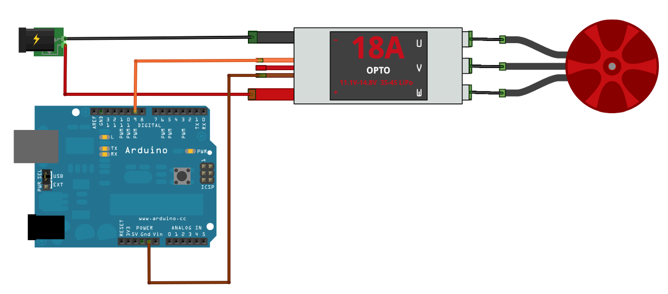
The electronic speed controllers (ESC's) are fairly straight forward to wire. The large red wire goes to one of the positive terminals on the power distribution board, and the large black wire goes to a negative terminal. When hooking up to the motor, the middle wire on the motor hooks up to the middle wire on the ESC. Then the two outside wires should be hooked up depending on which direction you want the motors to spin.
The brown wire connects to ground on the control board and orange hooks up to a PWM pin. On the Photon I used D0, D1, D2, and D3 as my PWM control pins. The red wire is 3.3vdc which can be used to power the controller. However, I chose to use the power supply on the distribution board.
Below is a diagram from the following link describing how to hook-up an ESC to an Arduino. http://robotic-controls.com/sites/default/files/images/esc_bb1.png
The ESC's I used in this project will accept 2S-4S lipo batteries. The S stands for how many cells there are. The more cells there are, the higher the voltage. Each cell has a nominal voltage of 3.7vdc. I chose to use a 3S battery pack which has a nominal voltage of 11.1vdc. I think the main advantage of higher voltage is that the wiring and electronics can be smaller due to lower amperage. I simply chose a 3S battery because I had one already, otherwise I would have went with a 4S.
Software/FirmwareControlling the ESC's is fairly simple, however they are a little confusing for a first timer. The ESC's emit beeps to communicate settings and states. If you don't know what these beeps mean it can be frustrating.
The first time you use an ESC you need to calibrate it, which is to say you need to tell it what the maximum and minimum control signals will be. Below in the code section you will find a script you can load on the Photon (or Arduino) to calibrate the ESC's. It simply writes a maximum value of 2000 microseconds to all of the ESC's on start-up. Then you will hear a pattern of tones coming from the ESC. After a delay of 5 seconds the script will write the minimum value of 1000 microseconds to all of the ESC's, thus completing the calibration.
There are many settings you can change on the ESC however I have not had the need to change any of them yet. Changing these settings are fairly complex and requires understanding a lot of audible patterns coming from the ESC's. A program card can be used to simplify the process.
The Photon code to control the drone uses the Servo library to control the ESC's using the writeMicroseconds()
command. When the Photon first boots up it needs to send the minimum control value (1000) to the ESC's. This will initialize the ESC's.
There are 5 Particle functions that can be called via the cloud. The first is "alt" which sets the speed of the motors. The next is "rot" which allows the drone to rotate. For example if the rot is set to 50, two of the motors speed up by 50 microseconds and 2 of the motors slow down by 50 microseconds, thus allowing the drone to rotate while maintaining lift. The third is "fwd" which allows the drone to fly in forward or reverse. This operates the same way as "rot", however on the "fwd" command two motors on the same side decrease speed and the other two speed up.
The last two functions are "idle" and "stop". These are direct commands that will either set all the motors to an "idle" speed (1100 microseconds in this case), or stop all motors.
The loop simply sets the motor speeds, factoring in the "rot" and "fwd" factors.
The html script allows the user to call the functions on the Photon and control the basic functions of the drone. At this point, my html code isn't very pretty or efficient but I'm not sure what I want to use as an interface, so it was good enough to get me going.
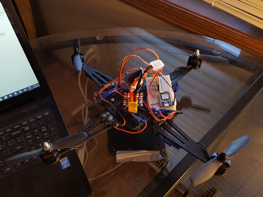
As you can see in the pictures above I 3-D printed a test rig that I could mount the motors and controls on for testing. It's not meant for flight but allowed me to test the control functions at my desk without flying away.
I also mounted it to a kitchen scale to see what the lift was for different settings. Below are the results, I stopped at 1600 microseconds because my test rig was becoming unstable. The results are fairly linear, so the performance from 1600 to 2000 microseconds could be extrapolated from the results.


Comments