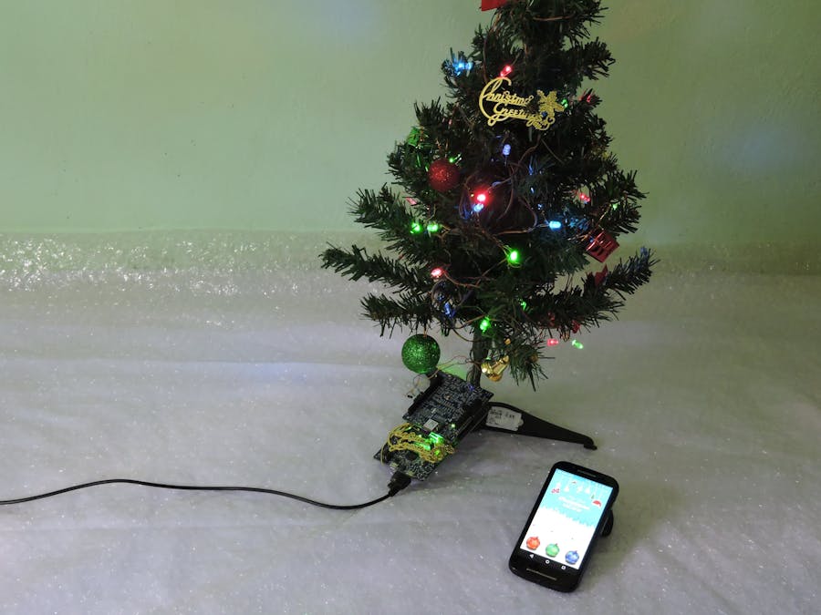
Ashok R
Published

Smart Christmas Tree

Create your own light shows with different patterns for the Christmas Tree via BLE

BeginnerShowcase (no instructions)24 hours563
Smart Christmas Tree

Things used in this project

Hardware components

NXP LPC54102 Development Sensor kit
×1
LED (generic)
LED (generic)
×24
X-Mas Tree (3feet)
×1

Software apps and online services

Android Application

Story

Read more

Schematics

Schematic

Code

Code

C/C++
/*
 * @brief Micro Tick timer example
 *
 * @note
 * Copyright(C) NXP Semiconductors, 2014
 * All rights reserved.
 *
 * @par
 * Software that is described herein is for illustrative purposes only
 * which provides customers with programming information regarding the
 * LPC products.  This software is supplied "AS IS" without any warranties of
 * any kind, and NXP Semiconductors and its licensor disclaim any and
 * all warranties, express or implied, including all implied warranties of
 * merchantability, fitness for a particular purpose and non-infringement of
 * intellectual property rights.  NXP Semiconductors assumes no responsibility
 * or liability for the use of the software, conveys no license or rights under any
 * patent, copyright, mask work right, or any other intellectual property rights in
 * or to any products. NXP Semiconductors reserves the right to make changes
 * in the software without notification. NXP Semiconductors also makes no
 * representation or warranty that such application will be suitable for the
 * specified use without further testing or modification.
 *
 * @par
 * Permission to use, copy, modify, and distribute this software and its
 * documentation is hereby granted, under NXP Semiconductors' and its
 * licensor's relevant copyrights in the software, without fee, provided that it
 * is used in conjunction with NXP Semiconductors microcontrollers.  This
 * copyright, permission, and disclaimer notice must appear in all copies of
 * this code.
 */

#include <stdlib.h>
#include <string.h>
#include "board.h"
#include "timer.h"

/** @defgroup PERIPH_UTICK_5410X UTick example
 * @ingroup EXAMPLES_PERIPH_5410X
 * @include "periph\utick\readme.txt"
 */

/**
 * @}
 */

/*****************************************************************************
 * Private types/enumerations/variables
 ****************************************************************************/

/*****************************************************************************
 * Public types/enumerations/variables
 ****************************************************************************/

/*****************************************************************************
 * Private functions
 ****************************************************************************/

/*****************************************************************************
 * Public functions
 ****************************************************************************/

#define ANG1_ON()   (Board_LED_Set(0,0))
#define ANG1_OFF() 	(Board_LED_Set(0,1))
#define ANG2_ON() 	(Board_LED_Set(1,0))
#define ANG2_OFF() 	(Board_LED_Set(1,1))
#define ANG3_ON() 	(Board_LED_Set(2,0))
#define ANG3_OFF() 	(Board_LED_Set(2,1))

extern UART_HANDLE_T *hUART;
int8_t acc_val[3]={'1','2','3'};

uint8_t rx_data[6];
uint8_t angle1=0,angle2=0,angle3=0;
volatile uint32_t msTicks=0;


struct Channel{

	volatile uint8_t ONTime;
	volatile uint32_t msPTicks;
	volatile uint8_t Set_Value;
	volatile uint8_t Enabled;
}ang1,ang2,ang3;

STATIC void setupClocking(void)
{
	/* Set main clock source to the IRC clock  This will drive 24MHz
	   for the main clock and 24MHz for the system clock */
	Chip_Clock_SetMainClockSource(SYSCON_MAINCLKSRC_IRC);

	/* Make sure the PLL is off */
	Chip_SYSCON_PowerDown(SYSCON_PDRUNCFG_PD_SYS_PLL);

    /* Wait State setting TBD */
	/* Setup FLASH access to 2 clocks (up to 20MHz) */
    Chip_SYSCON_SetFLASHAccess(FLASHTIM_20MHZ_CPU);

	/* Set system clock divider to 1 */
	Chip_Clock_SetSysClockDiv(1);

    /* ASYSNC SYSCON needs to be on or all serial peripheral won't work.
	   Be careful if PLL is used or not, ASYNC_SYSCON source needs to be
	   selected carefully. */
	Chip_SYSCON_Enable_ASYNC_Syscon(true);
	Chip_Clock_SetAsyncSysconClockDiv(1);
	Chip_Clock_SetAsyncSysconClockSource(SYSCON_ASYNC_IRC);
}


void Data_Init(){

	int i;

	ang1.Enabled = false;
	ang2.Enabled = false;
	ang3.Enabled = false;

	ang1.ONTime = 0;
	ang2.ONTime = 0;
	ang3.ONTime = 0;

	for(i=0;i<6;i++)
		rx_data[i]='0';


}

void delay(uint32_t dly){

	while(dly--);

}

/**
 * @brief	UTICK Interrupt Handler
 * @return	None
 */
void UTICK_IRQHandler(void)
{
	Chip_UTICK_ClearInterrupt(LPC_UTICK);

	msTicks++;
	//ROM_UART_Send(hUART,acc_val,3);


	//    			if(angle1 > 50){
	//Board_LED_Toggle(0);
	//    			}
}

/**
 * @brief	Main program body
 * @return	int
 */
int main(void)
{
	/* Setup SystemCoreClock and any needed board code */
	SystemCoreClockUpdate();
	Board_Init();

	/* Enable the power to the Watchdog Oscillator,
	   UTick timer ticks are driven by watchdog oscillator */
	Chip_SYSCON_PowerUp(SYSCON_PDRUNCFG_PD_WDT_OSC);

    /* First thing get the IRC configured and turn the PLL off */
    setupClocking();

    //Chip_Clock_EnablePeriphClock(SYSCON_CLOCK_PINT);
    //Chip_SYSCON_PeriphReset(RESET_PINT);
	/* turn INMUX clock off */
    Chip_Clock_DisablePeriphClock(SYSCON_CLOCK_INPUTMUX);

	/* Initialize the PinMux and setup the memory for ROM driver */
	uartrom_init();
	uartrom_config();

	/* Initialize UTICK driver */
	Chip_UTICK_Init(LPC_UTICK);

	/* Clear UTICK interrupt status */
	Chip_UTICK_ClearInterrupt(LPC_UTICK);

	/* Set the UTick for a delay of 1000mS and in repeat mode */
	//Chip_UTICK_SetDelayMs(LPC_UTICK, 1, true);

	Chip_UTICK_SetTick(LPC_UTICK,10,true);

	/* Enable Wake up from deep sleep mode due to UTick */
	Chip_SYSCON_EnableWakeup(SYSCON_STARTER_UTICK);

	/* Enable UTICK interrupt */
	NVIC_EnableIRQ(UTICK_IRQn);

	Data_Init();
	while (1) {


		if(msTicks >= 1100){

			ROM_UART_Receive(hUART,rx_data,6);
				msTicks = 0;
				ANG1_ON();
				ANG2_ON();
				ANG3_ON();

				ang1.Enabled = true;
				ang2.Enabled = true;
				ang3.Enabled = true;


			  				}
		else if((msTicks >= ang1.ONTime) && ang1.Enabled){

			ANG1_OFF();
			ang1.Enabled = false;

			}
		else if((msTicks >= ang2.ONTime) && ang2.Enabled){

			ANG2_OFF();
			ang2.Enabled = false;

			}
		else if((msTicks >= ang3.ONTime ) && ang3.Enabled){

			ANG3_OFF();
			ang3.Enabled = false;

			}

			if((rx_data[0] >= 0x30 ) && (rx_data[0] <= 0x39 ) ){
			ang1.ONTime = ((rx_data[1]-'0')*10) + (rx_data[0]-'0') + 60;
			ang2.ONTime = ((rx_data[3]-'0')*10) + (rx_data[2]-'0') + 60;
			ang3.ONTime = ((rx_data[5]-'0')*10) + (rx_data[4]-'0') + 60;

			}


		//ROM_UART_Receive(hUART,rx_data,9);

		//red_val = ((rx_data[1]-'0')*10) + (rx_data[2]-'0') +1;
		//green_val = ((rx_data[4]-'0')*10) + (rx_data[5]-'0')+1;
		//blue_val = ((rx_data[7]-'0')*10) + (rx_data[8]-'0')+1;


	}

	return 0;
}

Credits

Ashok R

Ashok R

37 projects • 102 followers
Hobbyist/Engineer/Director/Animatior

Comments