This project uses a thermistor to record ambient temperature. I wrote this when I received a thermistor in an IoT starter pack and was unable to find code that uses this as opposed to a proper temperature sensor.
A thermistor is a resistor whose resistance varies with temperature. This variation when measured can be used to calculate the temperature around the resistance.
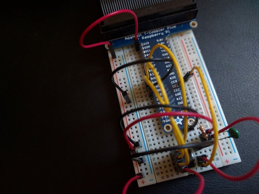
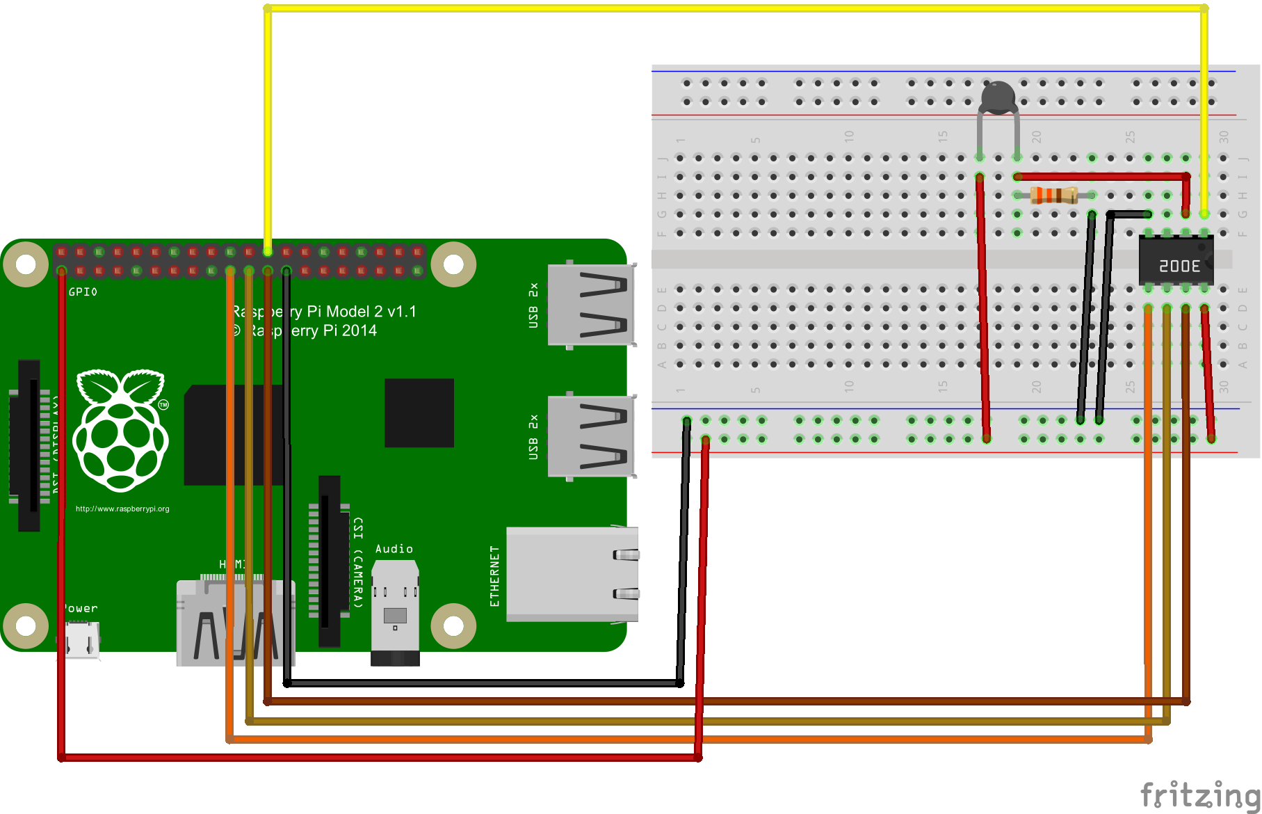
I used the setup shown in the diagram below with one minor difference. I used a pi-cobler to connect my pi to the breadboard as seen in the picture. However, I kept the diagram simple to avoid it getting too crowded.
ApproachSo let's get down to the details. The aim is to measure the temperature. To do this using the thermistor we need to know the value of it's resistance.
To measure resistance I built a voltage divider. Without getting too much into the theory of a voltage divider the idea is to set the circuit up so that the thermistor which is an unknown resistance is attached in series to a known resistance and the voltage between them is measured. The diagram below explains it much better than I ever could:
The formula that describes the setup above is:
Reordering for R1 since in our example R1 will be the thermistor gives us:
We supply 3.3V via the Raspberry Pi and attach a 1KOhm resistance in series to our thermistor. The ADC is connected between the two resistances. Refer to the complete setup schematic further below for help.
The ADC used was an MCP3002. You can use an MCP3008 as well as others but make sure to note the resolution. The MCP3002 is 10 bit. The MCP3002 is shown below:
As the circuit schematics below show, I connected the ADC ports in the diagram above to the Pi as follows.
- CS/SHDN to CE0.
- CH0 to one end of thermistor (this is the channel which we will get the voltage value from).
- Vss to GND.
- Din to MOSI.
- Dout to MISO.
- CLK to SCLK.
- Vdd/Vref to 3.3V.
As you can see above, I used the SPI bus on the Pi. We will revisit this when I go through code.
CalculationOnce we get the ADC value we need to convert that into voltage. The formula below shows the relation between ADC value and voltage:
Substituting variables we get,
Where n = 10 in our example,
Reordering for Vout we get,
Substituting Vout with this equation in Equation 2 in the previous section and solving we get,
Substituting the R2 value for our setup i.e. 1K Ohm,
This is the equation I will be using in code to calculate the thermistor resistance.
Once we have this resistance it's a matter of using the Steinhart-Hart equation to get the temperature. The equation is as follows,
Where T is temperature in Kelvin, R is the resistance R1 in Ohm and A, B and C are Steinhart-Hart coefficients. These depend on the model of the thermistor and the temperature range of interest. This was the painful part. The thermistor did not come with a spec sheet nor was it identified in the part list so I had to dig around different suppliers and finally found the one that the pack used. Got A, B and C from those. These are the values I used in the example. For your project you might have to change these.
CodeFinally, we get to the good part. The code was written in C# using VS 2015. The key reference to add to the project is Windows IoT Extensions for the UWP. Make note of the following using statements in the StartupTask.cs file:
using Windows.Devices.Spi;

using Windows.Devices.Enumeration;
After the setting up formalities there a key number of things we have to do. The first is initialising the SPI device. This is done through an SpiConnectionSettings object.
var settings = new SpiConnectionSettings(SPI_CHIP_SELECT_LINE)

{

    ClockFrequency = 500000, /* 0.5MHz clock rate */
    Mode = SpiMode.Mode0 /* The ADC expects idle-low clock polarity so we use Mode0 */
};
The SPI_CHIP_SELECT_LINE is an int and will be 0 in this case. This is because we attached the ADC to the CE0 pi pin.
These settings are then used to initialise the SPI device as follows:
string spiAqs = SpiDevice.GetDeviceSelector(SPI_CONTROLLER_NAME);

var deviceInfo = await DeviceInformation.FindAllAsync(spiAqs);

_spiAdc = await SpiDevice.FromIdAsync(deviceInfo[0].Id, settings);
Note that _spiAdc is a field of type SpiDevice in the source code and SPI_CONTROLLER_NAME is a string with value "SPI0".
Once we have the SPI device it is a simple matter of reading the buffer on the SPI device:
byte[] readBuffer = new byte[3];

byte[] writeBuffer = {0x68, 0x00, 0x00};
_spiAdc.TransferFullDuplex(writeBuffer, readBuffer);

int adcValue = ConvertToInt(readBuffer);
//This is based on Voltage Division

double rV = ((1024D/adcValue) - 1D)*1000D;
//Steinhart-HartEquation inverted

double tempK = 1/(9.6564E-04 + (2.1069E-04*Math.Log(rV)) + (8.5826E-08*Math.Pow(Math.Log(rV), 3)));
 double tempC = tempK - 273.15;
Note the read buffer length and write buffer values of 0x68, 0x00 and 0x00. These are specific to the ADC in us. In this case these are for the MCP3002. Please look up the values for your MCP.
By the way, the temperature calculated above is in Celcius! For those of you who prefer Fahrenheit, please feel free to further convert it.
ConclusionHope this makes the job of using a thermistor to read temperature a little bit easier. Please have a look at the source code in the linked git repository for the full example. Note that the example also has functionality to upload the temperature readings to an Azure IoT hub. More on that in another post. Also, please feel free to correct me and provide feedback.


Comments