

Hardware components | ||||||
 |
| × | 1 | |||
| × | 1 | ||||
 |
| × | 1 | |||
| × | 1 | ||||
| × | 1 | ||||
| × | 1 | ||||
| × | 1 | ||||
| × | 1 | ||||
| × | 1 | ||||
| × | 1 | ||||
| × | 1 | ||||
| × | 1 | ||||
| × | 20 | ||||
| × | 2 | ||||
| × | 1 | ||||
Software apps and online services | ||||||
 |
| |||||
In this project, I choose the electric solenoid lock as the box switch. If there is no press in keys for 3 minutes, the box will enter the sleep mode. Press the key 1 will wake up the box and send IoT order to open the box via the module OBLOQ. Once the IoT platform receives, it will decide to send or not send the order to open the box. When the box is awake, it will send the status data(Open/ Closed), the object thickness (with a ultrasonic distance detector) and the object weight (with a digital weight sensor). These key parameters can prevent some smart children cheating works. The reason why we set password is that it can be directly opened when adults at home. The 3 colors RGB LED (Blue, Green, Red) module is in the front of the box. When Blue is ON, suggesting the device is awake; When Green is ON, which suggests the box will be unlocked immediately; When Red is ON, which means the password is wrong. Well, the LED is OFF, means the box enters the sleep mode.
Function ShowsSmartphone Remote Control Box Open: The phone receives the request from the box, the input 0123456789A in the IoT platform and click send, box is open. Now, kids can play iPad and phone.
Computer Remote Control Box Open: The principle is same as the smartphone.
IoT platform real-time monitor data:
Active by password sleep mode:
Working when awake:
Input wrong password:
Below are two Gravity ultrasonic modules developed by DFRobot, the left is the analog one, the right is the IIC module. Th IIC Gravity ultrasonic module not just can detect distance but also temperature.
The relay and the electric solenoid lock should be used together. Because the lock is powered by the external supply 9-12V to Open / Cloze and Uno controls the relay to control the circuit of lock.
NOTE: The electric solenoid lock cannot be powered for long time. You’d better cut power when the action is finished. Otherwise, the longtime power ON will lead to heating and damage.
There is a metal poke rod on the upper right corner. Poke it manually, the lock will be unlocked and its lock latch will spring out. The are 3 mounting holes in the main body, you can fix it to other objects. The holes are compatible with M3 screws. The lock accessories have 1 DC power wire and 1 DuPont transfer wire. Connect the transfer wire to I0 of UNO, then you can pass the states data to UNO.
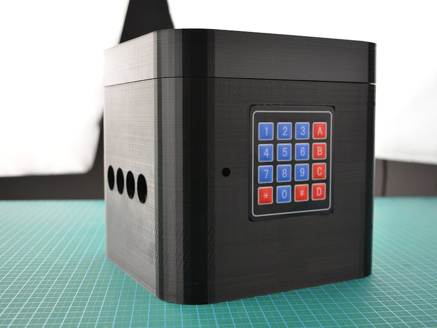
This is a 4x4 membrane keyboard. There is adhesive in the back, which can be pasted to anywhere. The maximum thickness is 1.23mm, and it has 8 pins which all are marked with numbers, the leftmost is 8 and the rightmost is 1. Pins 8-5 control rows, 1, 2, 3, 4 in order; while pins 4-1 control columns, 1, 2, 3, 4 in order. Select the resister in the multimeter, connect 2 ends to pin8 and pin4, press the key2, the resistor value will reduce to 3K Ohm around; connect 2 ends to pin8 and pin3 and press the key2, the result is similar. When Uno scanning the pin level, it suggests the key in correspond is pressed. The hardware eliminate jitter is designed in the inner part, so you can read the pin level directly.
The digital weight sensor contains 1 PCB and 1 aluminum block. In the block, there are 2 M5 screw holes in the left to fix position and 2 M4 screw holes in the right to fix the pallet. In the middle position is a sensor, once the block bears load, the sensor can figure out the weight by the tension. It can handle weight within 1kg, the precision is 0.1g.
This digital RGB LED module is compatible with WS2812 control. The right side is the input, the left is the output. With pins and Dupont header connect, it can be easily connected one by one to realize decoration lights effect.
In the inner of the box, the front side has a position to install LED module (Left), you just need to fix LED at here with a self-tapping screw.
The button, please place as below and use M5x10 self-tapping screws to fix modules into the board one by one, OBLOQ module, gravity weight sensor, relay and UNO, expansion shield.
There are 2 M5 screw holes in the left of the aluminum block, using M5x20 screws (with nut) to fix it into the button board.
Place nuts to the 2 hexagonal holes in the button and seis up.
Taking the screw to go through the aluminum block in the inner part and twist it tightly into the nut to fix the aluminum block.
Then install the electric solenoid lock, put 2 M3x18 screws and nuts to the hexagonal holes in the button and seis up.
Pull the lock down in the inner and fasten it to the position to install and fix with 2 M3x18 screws.
This wire header is installed to the round hole in the back. The type I chose has a circle step, so it can be directly fixed by pressing it form the inner to the outside. Well, it will be fastened better if added with some hotmelt adhesive. The header is to connect the external supply. 2 males are to supply power to the lock and UNO, 1 is to the power supply wire of the lock, the other is to DC supply interface of UNO.
Taking 8 Dupont wires, the male header to 8 wires of the keyboard and stretch to IO interfaces of UNO.
Check the diagram as below and connect all parts accordingly.
Put all wires to 2 slots, if wires are too many to put, you can try putting the thick ones, and pressing others with them.
Modify the WIFI name (WIFISSID), Wi-Fi password(WIFIPWD), IOT platform(SERVER), IOT ID(IOTID), IOT password(IOTPWD), device number(TOPIC) and the password to open the box (number within” ” in the adminPassword ) according to your own, I set the password to 0123456789A and confirm it via pressing the key #, and uploading the code:
Taking 2 M4x35 screws to go through the pallet and fix them to 2 M4 screw holes in the aluminum block to handle the pallet.
The work is done, plugin the external power supply and the box begins to work.
That is all, thanks for your reading and welcome share this post.

Comments