


Hardware components | ||||||
 |
| × | 1 | |||
_ztBMuBhMHo.jpg?auto=compress%2Cformat&w=48&h=48&fit=fill&bg=ffffff) |
| × | 1 | |||
 |
| × | 2 | |||
| × | 1 | ||||
| × | 1 | ||||
 |
| × | 1 | |||
 |
| × | 3 | |||
 |
| × | 3 | |||
 |
| × | 1 | |||
 |
| × | 1 | |||
| × | 8 | ||||
| × | 1 | ||||
| × | 1 | ||||
| × | 1 | ||||
| × | 1 | ||||
Software apps and online services | ||||||
| ||||||
 |
| |||||
Hand tools and fabrication machines | ||||||
 |
| |||||
 |
| |||||
| ||||||
Hand/Wrist/Finger Free, Arm Only Control
The idea is to develop a Robotic Car which will be controlled by NXP Freedom (FRDM-K82F) board that has Kinetis K82F MCU (ARM Cortex M4) and FXOS8700CQ - accelerometer+magnetometer.
User can control the Speed & Direction by the movement of K82 Board mounted on his/her forearm. Gesture movement is interpreted by the Accelerometer and converted into command.
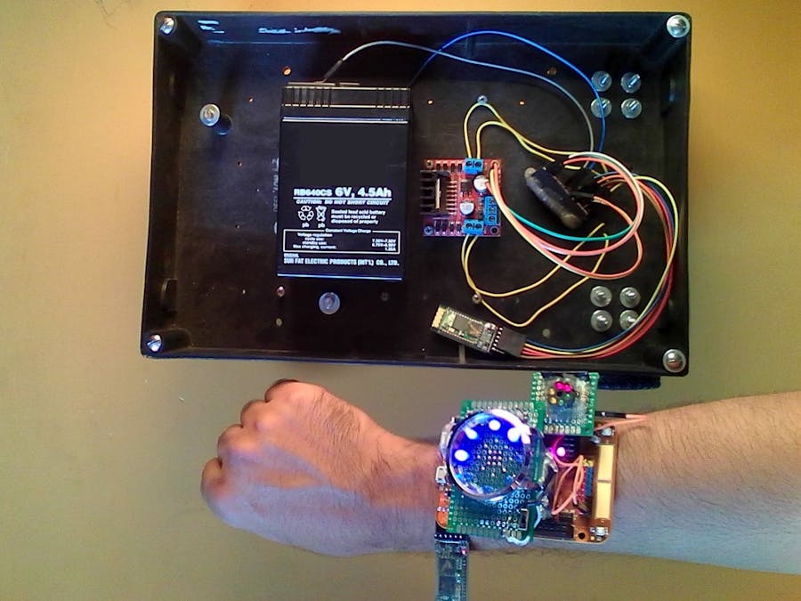
The Robot will be powered from a 4500 mAh 6 volts maintenance free Lead Acid Battery and the K82 Freedom Board will be powered form a homemade Power Shield with LED Display.
Live ActionThere is a 5 Volt Power Bank in my hand, nothing fishy here !!! The LiPo Battery on the shield was low during the video recording, so I had to power it form external power pack !!
The response slightly lags probably because of Arduino Serial.AvailableUntil () function and low baud rate
Real Life Application: Electronic Wheel Chair Driving with Arm only DisablesThink about a disable person with no hand or leg. Without hand that person cannot drive a wheel chair. But with the hardware I made, it would be possible for him/her to drive an electronic wheel chair by attaching the Bluetooth Gesture Controller on Forearm.
Although, real life application requires more concern with safety, security, and quality. For safety of embedded system requires watchdog interrupt to avoid frenzy state, Real Time Response (by replacing Arduino with 32 bit ARM ) and Improved code.
For Security, K82 Board’s Encryption Features can be used with Gesture Password.
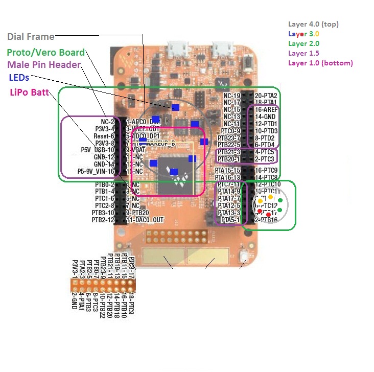
Getting Started with NXP K82 Freedom BoardTo start with this Freedom K82 Board manual to know which pins are connected to RGB LED, Switches, Accelerometer, Jumpers and Power Options !
To know about Electrical Characteristics (voltage, current, power, frequency etc) of the MCU check this datasheet.
The K82 Sub-Family Reference Manual (MCU on Freedom K82 Board -K82P121M150SF5) has 2213 pages , which is quite overwhelming for hobbyist.
Very well explained instruction, 10 times better than the Webinars :
Getting Started Videos Freedom K82 Videos
A better way to learn is to watch Kinetis K Series MCU Online Training
There are APIs(functions) to do things, so you don't need to dig into Register Level of ARM. Check this API guide to understand how to write codes :
About Kinetis Design StudioThe Kinetis Design Studio (KDS) is a free IDE for Kinetis MCUs that enables creating, compiling and debugging Embedded Designs for Kinetis MCUs.
Here are some snapshots of most frequently used files/folders in KDS. On the left most column are the projects files directory.
Source folder ( which is a sub directory of project folder) contains the main.c code. By clicking, it will show up in the middle editor window.
Most frequently used Build, Flash, Debug options are here :
Segger J-Link Debugger tab contains the flash files of all the build projects :-
KDS allows programming in C/C++ with high level APIs/Functions and Peripheral Drivers.
Here is a Block Diagram of KDS from NXP's -
Here is a quick overview of the Kinetis K82 Freedom Board from Freedom Board for Kinetis K82F Hardware (FRDM-K82F) User's Guide :
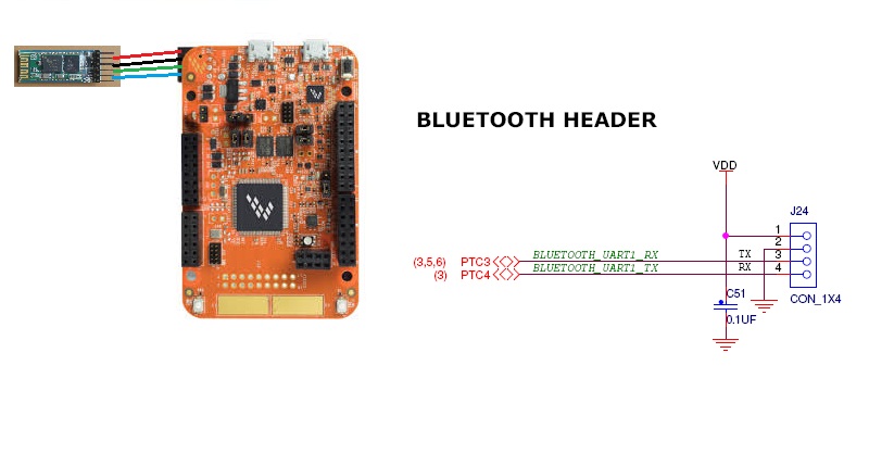
The FRDMK82F board features the MK82FN256VLL15 MCU, which boasts a maximum operation frequency of 150 MHz, 256 KB of flash, a 256 KB RAM, a full-speed USB controller with available crystal-less operation, and analog and digital peripherals. The FRDM-K82F hardware is form-factor compatible with the ArduinoTM R3 pin layout, providing a broad range of expansion board options. The onboard interface includes a six-axis digital accelerometer and magnetometer, an RGB LED, FlexIO header, and sufficient footprint to add an optional Bluetooth module (for use over UART) and RF module (for useover SPI).
The FRDM-K82F platform features OpenSDAv2.1, the Freescale open-source hardware embedded serial and debug adapter running an open-source bootloader. This circuit offers several options for serial communication, flash programming, and run-control debugging. OpenSDAv2.1 is an mbed™ HDKcompatible debug interface preloaded with the open-source CMSIS-DAP Interface firmware (mbed interface) for rapid prototyping and product development, with a focus on connected Internet of Things devices.Important!
Some pins are used to connect on-board resources (Switch, LED, sensor), be careful about these pins, while setting I/O.
Stuffs Needed to Make ThisSome images of the devices, modules, tools used in this project :-
I have got this nice looking vintage Intercom Box as family heirloom from the 90', which I am going to use as the chassis for the thing.
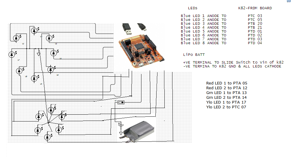
Red, Green, Yellow LEDs two of each color are soldered in circular pattern on a protoboard with all the cathodes through 1K resistance to Ground. 1k Network Resistor is used.
The Plastic Circular Ring is salvaged from a 6 Color Pen .
8 Blue LEDs are soldered in a Circular Fashion on Protoboard and all the Cathode terminals (-) are soldered to Gnd Pin.
Next, Male Pin Headers are soldered, RED for Vin, 3.3 V, 5V (any + Rail), Black for Ground (-) and Yellow for I/O.
Heat Shrink Tube, Hot Glue, Hookup Wires are used to Route the connections, LiPo Battery is placed beneath the board.
Step 2: The Cart: Gear Motors, Nuts & BoltsUsing the Drill-Motor some holes are made on the Intercom Box, Then Motors are mounter with Nuts & Bolts, Gear Motor Mountings and a pair of Eraser to absorb shock.
Next, solid core wires are solders and routed to the other side.
A 360 Degree rotating front wheel is attached to the box to complete the mechanical parts installation.
After putting all the pieces the car will look something like this :
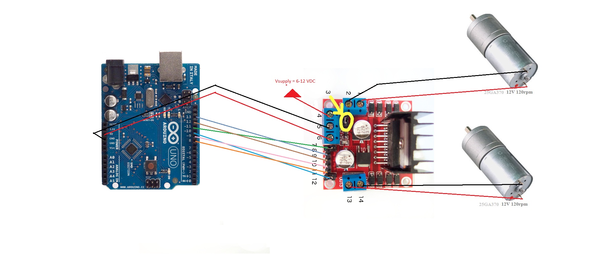
Finally the motor wires are connected to the L298 Motor Driver module.
Step 3: HC-05 Bluetooth as Master/Slave2 HC-05 Bluetooth module are used to connect a wireless serial link. HC-05 module directly plugs into Freedom K82's Bluetooth Header.
By default, HC-05 modules are configured in slave mode and Baud rate of 9600 bps.
One of the HC-05 module is connected to PC using a USB-to-Serial module by press and holding the switch on HC-05 before powering it up to Enter AT Command Mode. Then release the switch once powered up. The Red LED on HC-05 will blink slowly (once every two second).
The on the serial terminal ( I used Arduino IDE Serial Monitor ) Baud of 38400 and Both NL & CR for configuring purpose of the device.
Then Following AT command are issued one by one : -
AT+RMAAD
AT+ROLE=1
AT+RESET
Enter again in AT Command Mode by pressing & holding the switch.
AT+CMODE=1
CMODE=1
AT+UART=115200,0,0
AT+INQM=0,5,5
Now one of the HC-05 is Master with 115200 serial link baud rate.
For the other HC-05 following AT Commands are issued :-
AT+RMAAD
AT+ROLE=0
AT+UART=11500,0,0
Here is a nice tutorial about how to do this.
The Master HC-05 is connected to K82 Freedom Board and the Slave HC-05 is connected to the (Arduino Bootloaded) AVR ATmega8A/168/328P 8 bit 16 MHz MCU.
Step 4: Do as Kinetis Command'sThis is a homemade Arduino Uno Clone made with AVR ATmega8A/328P.
Supports full Arduino functionality.
It receives Wireless Commands over Bluetooth-Serial Link and performs accordingly.
PWM and GPIO controls the L298 Driver which drives the motor as per command. Serial polls to get commands received from K82 Board.
Working Principle: Accelerometer BasicsAn accelerometer is an electromechanical sensor that will measure acceleration forces like (Natural) Gravitational Force or Movement/Vibration Force.
There are many different ways an accelerometer can work. Some accelerometers has piezoelectric microscopic crystal structures that get stressed by acceleration, which causes a voltage to be generated. Another way to do it is by sensing changes in capacitance of micro-structures MEMS next to each other, they have a certain capacitance between them. If acceleration force changes on the structures, then the capacitance will change, which can be converted from capacitance to voltage.
Here is an illustration of accelerometer from WikID
We know , Gravitational Acceleration is 9.81 m/s^2 on a flat surface ! If the surface is tilted then this acceleration will split into perpendicular and horizontal component.
By doing some trigonometric calculation the tilt angle can be measured. This Tilt Angel ( which is a Gesture of forearm ) can be programmed as User Input to operate something. This is the working principle of this project.
Building the SoftwareThe software is based on the bubble example of NXP K82 Freedom Board, which is the demo program comes with each newly shipped board.
I have made my project by changing and adding codes to that program's source codes.
- The main.c file has the #included header files , defined constants, global variable, function prototypes
- In the main loop first I/O pins are initialized, module clocking are enabled, configuration for peripherals are loaded.
- In the infinite while loop some of the control functions are sequentially called to get new acceleration data, calculate angle, RGB PWM, Gear/Acceleration Dial, send command over LPUART to Bluetooth etc.
The bubble.c which is an example acceleration sensor app shows Pitch and Roll of the Board with Green/Blue LEDs. This example is changed and new codes are added to adapt for the project .
Here are the changes in pin_mux.c explained pictorially -
Most important part of K82 Sub-Family Reference Manual is from page 213-222 where Pin Muxing Information is available.
Following Peripherals of K82 MCU are utilized :
FlexIO FTM Module >> to create PWM to Drive onboard RGB LED
GPIO Module >> to Drive Dial Display to represent Gear & Acceleration
LPUART Module >> to Establish Bluetooth Serial Link
I2C Module >> to Fetch Accelerometer Data from Sensor
UART Module >> to do Serial Debugging
ConclusionThis project demonstrates some interesting application of Accelerometer for Controlling Vehicle. There is more scope of improvement and more work required for transforming form project to product like gesture controlled wheel chair.


_3u05Tpwasz.png?auto=compress%2Cformat&w=40&h=40&fit=fillmax&bg=fff&dpr=2)

Comments