


Hardware components | ||||||
| × | 1 | ||||
_wzec989qrF.jpg?auto=compress%2Cformat&w=48&h=48&fit=fill&bg=ffffff) |
| × | 1 | |||
 |
| × | 1 | |||
 |
| × | 1 | |||
 |
| × | 1 | |||
| × | 14 | ||||
| × | 1 | ||||
Software apps and online services | ||||||
 |
| |||||
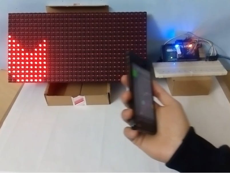
What makes some shows and some movies are so exciting?
The answer is the effects. I loved the luminous lightsabers in Star wars and the fantastic blue suit of superhero Max Steel. When I used some simple LEDs in my project, I discovered that they can color the world and mimic what they do in the shows. So I decided to get into this lovely, fantastic world with something (maybe) new! I created a simple design and made it move with my hand by using my phone and very simple components.
If it is your first time using Arduino, you should download the Arduino coding software to can talk to your Arduino.
Step 2: Download the Matrix Libraryhttps://github.com/freetronics/DMD2
This one is better and easier than the one on the "free electronics" site.
Step 3: Download 1Sheeld Libraryhttps://1sheeld.com/downloads/
Step 4: Download 1Sheeld App on Your PhoneFrom the app store or https://1sheeld.com/downloads/
Step 5: Extract FilesAfter you successfully downloaded the libraries, extract the files in Arduino's library directory: Path\UserName\Documents\Arduino\libraries. And rename them DMD2 and oneSheeld.
Enter the DMD2 library and replace the file DMD2.cpp with the one attached at the end of this project. It is only changed to work with mega different pins.
Step 7: Connect 1SheeldConnect your 1Sheeld board by following this link: https://1sheeld.com/tutorials/getting-started/
Step 8: Connect LED MatrixIf INPUT is not labeled, look for one or more arrows pointing in the horizontal direction (ignore any vertical arrows, whether up or down). The horizontal arrows show the direction data moves from INPUT to OUTPUT — that way you know which connector is which.
To understand the ribbon connector, visit this link: https://learn.adafruit.com/32x16-32x32-rgb-led-matrix/connecting-with-jumper-wires
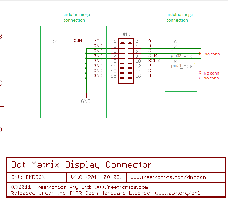
Then connect the pins to Arduino as shown in the schematic photo.
Step 9: Upload the Code onto ArduinoAfter connecting, we are ready to use the code. So connect Arduino to your computer and upload the code in the attached code file at the end of this project.
Step 10: Use the 1Sheeld AppOpen your app and connect with 1Sheeld. Activate the accelerometer and click on the upper right triple-shield sign to see the values of your motion. Move your phone with hand to left and to right.
Small note:
The accelerometer is an acceleration sensor designed to calculate the simplest changes in the rate of movement in a certain direction. But, for this device, existing applications today are interested making a Transducer for movement and positioning.
Now you can enjoy it.
Finally:If there are any questions, suggestions or comments, it is my pleasure to answer them and to learn from you.
I hope you are able to replicate it and make it better. And that you can make this swimmer reach the final wave. ^_^


Comments