


In this tutorial, we'll walk you through the quick assembly and programming of a high-powered LED Beacon featuring Wi-Fi localization capabilities. This project is centered around the ESP32-S2-SOLO-2-N4R2 processor, enabling the creation of a Wi-Fi hotspot for accurate localization. Let's dive into the straightforward steps to bring your LED Beacon to life.Step 1: Hardware introduction
The ESP32-S2-SOLO-2-N4R2 chip is at the heart of this project, offering the following features:
· Protocol Supported 802.11 b/g/n
· 2.4 GHz frequency band
· Interfaces: I2C, I2S, SPI, UART
· 128 KB ROM
· 320 KB SRAMStep 2: Bill of materials
Follow a clear schematic diagram, outlining connections between the ESP32 chip and the high-power LED diodes. This visual guide is crucial for the subsequent assembly steps.
Design of two-layer PCB layout based on the schematic. Proper spacing, alignment, and connections are key to a smooth assembly process.
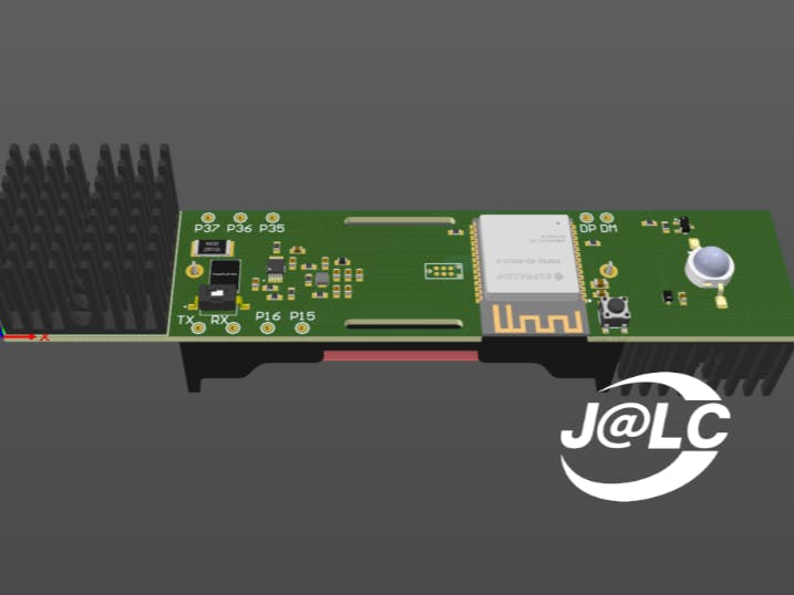
3D model to visualize how all components fit together. This step aids in identifying and rectifying any potential design issues and shows how assembled PCB is going to look like.
We are incluging a sample code snippet for programming the ESP32-S2-SOLO-2-N4R2 chip, allowing control over the flashing patterns of the high-power LED diodes and setting up a hotspot. This adaptable code ensures customization according to individual preferences.
Step 7: Order your PCB from JLCPCBFollow this steps to order your own PCB: https://jlcpcb.com/HAR
With your components prepared, follow these steps to assemble and program your LED Beacon quickly. This DIY project not only enhances your understanding of electronic circuits but also lets you create a customized LED Beacon with Wi-Fi localization capabilities. Happy building!


Comments