


Hardware components | ||||||
 |
| × | 1 | |||
| × | 1 | ||||
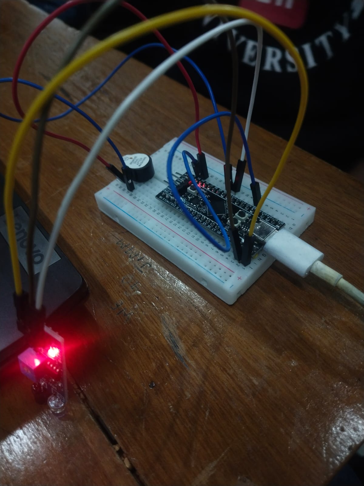
In this guide, we'll explore programming the STM32 "Black Pill" development board using STM32CubeIDE to create various LED blinking sequences.
Materials Needed:- STM32 Black Pill board
- USB to Mini-USB cable (for both programming and power supply)
- Three LEDs
- Breadboard and jumper wires
- STM32CubeIDE (Download and install from the STMicroelectronics website)
- Launch STM32CubeIDE and start a new project.
- Select "New STM32 Project" from the Quick Start menu.
- Choose your board or microcontroller (STM32F103C8) and proceed.
- Specify project name and location, then complete the setup.
- In STM32CubeIDE, go to the "Pinout & Configuration" section.
- Configure three GPIO pins to control LEDs (e.g., GPIOA Pin 0, Pin 1, Pin 2 for Red, Green, Blue LEDs).
- Set these pins as GPIO Outputs and activate GPIO clock.
- Navigate to the "Core" directory in the project explorer and access main.c.
- Include necessary libraries and set up the initial environment.
cCopy code
HAL_GPIO_WritePin(GPIOA, GPIO_PIN_5, 0);
HAL_GPIO_WritePin(GPIOA, GPIO_PIN_6, 0);
HAL_GPIO_WritePin(GPIOA, GPIO_PIN_7, 0);
HAL_Delay(1000);
HAL_GPIO_WritePin(GPIOA, GPIO_PIN_7, 1);
HAL_Delay(1000);
HAL_GPIO_WritePin(GPIOA, GPIO_PIN_6, 1);
HAL_GPIO_WritePin(GPIOA, GPIO_PIN_7, 0);
HAL_Delay(1000);
HAL_GPIO_WritePin(GPIOA, GPIO_PIN_6, 1);
HAL_GPIO_WritePin(GPIOA, GPIO_PIN_7, 1);
HAL_Delay(1000);
HAL_GPIO_WritePin(GPIOA, GPIO_PIN_5, 1);
HAL_GPIO_WritePin(GPIOA, GPIO_PIN_6, 0);
HAL_GPIO_WritePin(GPIOA, GPIO_PIN_7, 0);
HAL_Delay(1000);
HAL_GPIO_WritePin(GPIOA, GPIO_PIN_7, 1);
HAL_Delay(1000);
HAL_GPIO_WritePin(GPIOA, GPIO_PIN_6, 1);
HAL_GPIO_WritePin(GPIOA, GPIO_PIN_7, 0);
HAL_Delay(1000);
HAL_GPIO_WritePin(GPIOA, GPIO_PIN_6, 1);
HAL_GPIO_WritePin(GPIOA, GPIO_PIN_7, 1);
HAL_Delay(1000);
- Connect your STM32 Black Pill board to your computer using a USB cable.
- Build the project by clicking on the hammer icon in the toolbar.
- Once built successfully, flash the code onto the board by clicking the play (debug) button.
- After flashing is complete, observe the LED blinking patterns displayed by your Black Pill board.
- LEDs will blink according to the defined patterns within the main loop.
By following these steps, you've programmed your STM32 Black Pill board to control LEDs in various blinking sequences using STM32CubeIDE. For further exploration, consider creating new patterns or modifying the existing code to achieve more complex LED arrangements.


Comments