


Hardware components | ||||||
 |
| × | 1 | |||
| × | 1 | ||||
| × | 1 | ||||
| × | 1 | ||||
| × | 1 | ||||
| × | 1 | ||||
| × | 6 | ||||
| × | 3 | ||||
| × | 1 | ||||
Software apps and online services | ||||||
| ||||||
 |
| |||||
 |
| |||||
 |
| |||||
| ||||||
| ||||||
| ||||||
| ||||||
| ||||||
| ||||||
| ||||||
| ||||||
Hand tools and fabrication machines | ||||||
 |
| |||||
| ||||||
Antibiotic resistance is one of the most important contemporary challenges to global health and food security. Getting more frequent and increasingly perceptible threat to patients, it can touch anyone. Antibiotic resistance is not a new phenomenon that has only emerged after the use of antibiotics in medicine. The inappropriate use of antibiotics in humans and in the food industry speeds up this process considerably. The effectiveness of antibiotics is not forever. Therapeutic options are running out, causing rising mortality from resistant microbes infections.
Based on the World Health Organization report “TACKLING DRUG-RESISTANT INFECTIONS GLOBALLY: FINAL REPORT AND RECOMMENDATIONS” from May 2016, domain experts estimate that by 2050, 10 million lives a year and a cumulative 100 trillion USD of economic output are at risk due to the rise of drug resistant infections if we do not find proactive solutions now to slow down the rise of drug resistance.
Bacteriophages as perfect predatorOne of the promising alternatives to antibiotics therapy is Bacteriophage Therapy (Phage Therapy). It is crucial in the era of multi-drug resistance of pathogenic bacterias and a decreasing number of therapeutic options.
The bacteriophages are viruses that infect bacteria by coding specific enzymes that degrade the bacterial cell wall by specific receptors and tail fibers to hijack the host cell’s cellular machinery for their own replication.
Unlike antibiotics, bacteriophages tend to be highly specific in their action, targeting intended pathogens while leaving commensal bacteria alone. Antibiotics are much more indiscriminate since they kill the good bacteria along with the bad ones.
Another great advantage is the fact that thanks to the humble phages a human insulin was safely and cheaply produced for the first time. It has also opened up many applications such as high throughput screening of clones, nanomaterial development, antibacterial treatment for food items, as a diagnostic tool and drug discovery. The most recognizable examples of phage success application in healthcare come from UK - a british teenager has made a remarkable recovery after being the first patient in the world to be given a genetically engineered bacteriophage to treat a drug-resistant infection (DOI: 10.1038/s41591-019-0437-z), and US where a man was diagnosed with a multidrug-resistant bacterial infection in his pancreas and finally was treated successfully with bacteriophages. More confirmed examples were described in Phage Therapy: A Practical Approach book (Springer Nature, 2019).
The phages infect bacterial cells and they can enter into them in one of two distinct ways called lytic or lysogenic lifestyles. During a lytic lifestyle a phage infects a bacteria - its genome is replicated many times - and the newly created copies are released into the surrounding environment through lysis.
The lifestyle of a phage is identified by culturing and isolation in the lab by spreading of phage infection of bacteria agar plates and making spot tests.
Spot tests is a quick way to check whether a phage sample can infect a bacterium by placing a small drop or “spot” of phage onto a plate inoculated with the bacterium. This test will determine if the putative plaque will propagate phage. Identifying and verifying putative plaques is crucial for conventional Phage Therapy which relies on strictly lytic phages.
InspirationThe classification of the type of lysis resulting from a phage application is frequently performed by specialists based on visual observations. This time-consuming and potentially biased task could be simplified using semi-automated inhibition zone readers which are dedicated for bacterials colony counting only.
However, most bacterial colony readers are very expensive and need to have embedded software that requires significant changes in laboratory workflows. In addition, the information pertaining to the images is not always recorded in a standardized manner. Furthermore, existing colony counters are not dedicated for phage lysis. Finally, they’re not available for schools and universities for educational purpose, because of the high price and non existing support for this kind of stakeholders.
We care about healthcare and we cannot accept the risks of antibiotic resistance. That is why our crew decided to support Phage Therapy research as best as we can.
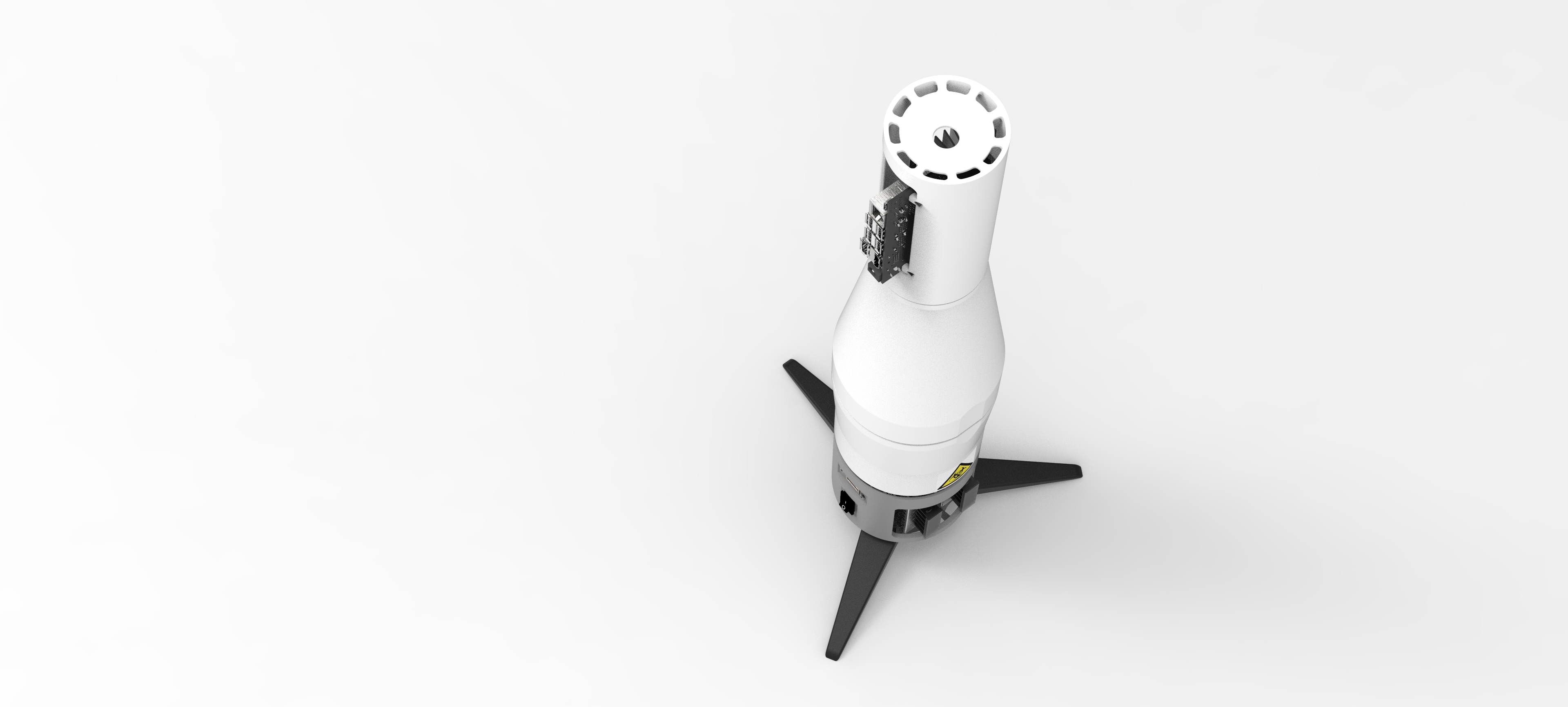
We analysed the existing workflows employed by phage microbiologists and biotechnology students from different parts of the world, to determine how they analyze phage susceptibility of bacteria. After days of online meetings and discussions, exploring state of the art publications on PubMed, we have designed a comprehensive system called Virus Activity Detector for Education and Research (VADER).
This system easily automates measurements of phage activity in spot tests which improves the discovery process of lytic phages.
VADER device was designed and 3D printed from scratch to lead to a higher degree of traceability and better data standardization as well as to improve stability of model predictions. To reduce costs as much as possible and deliver embedded AI powered computer vision support - which did not require continuous internet connection to real time work - we decided to use NVIDIA Jetson Nano and Arducam camera module.
VADER software is an Open-Source, Deep Learning and NVIDIA JetPack SDK based imaging system designed for making highly reproducible, high temporal resolution images from Petri dishes for accurate bacteriophages spot tests and their deeper analysis and classifications.
VADER allows you to make a picture of the petri dish with phage colonies, immediately detect the number of spots, mini-spots and assign them specific class label with probability value (%), which at the end inform you about the phage effectiveness for the bacterium tested.
What deserves emphasis is that the VADER system can be adapted easily to other types of agar plates and characteristics (examples above). Our system can work as a tool for observation of self-prepared bacterial colonies.
You can grow your own cultures using many guides, for example: HOW TO GROW BACTERIA AND MORE
Life Science needs hackers!We’re grateful for our team member Iwona for discovering the Hackster challenge. Her idea to build a diverse, multidisciplinary team from different countries was the best thing that happened to us. Yana, another crew member, prepared many Deep Learning models based on different neural network architectures. Her final idea to use Transfer Learning blew our minds when we saw the accurate results of prediction with the model which could be applied into NVIDIA Jetson Nano. After that moment Wojtek, Marcin and Piotr started building VADER to embed everything into one, coherent, low-cost system.
What's next?To release its full potential, VADER needs to be supported by a dedicated web platform for data organization and global phage community collaboration. We’re going to build and integrate it with each future VADER instance by securing REST API. and demonstrate on domain conferences.
We also started to sharing the system with schools and university biotechnology and data science clubs in our area to validate the educational value of the system.
We intend to develop the VADER platform further, improving its fabrication, assembly and handling. It is vital to create a community interested in microbial observation, especially for educational purposes. With infections spreading around the world with the speed of an airliner, our first line of defence is knowledge.
Create VADER by yourselfWe want you to be able to create VADER from the scratch, as we did. That's why we prepared detailed technical documentation which covers:
- Device overview
- Setting and using (Hardware and Software setup)
- Safety
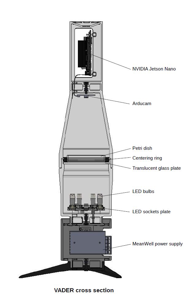
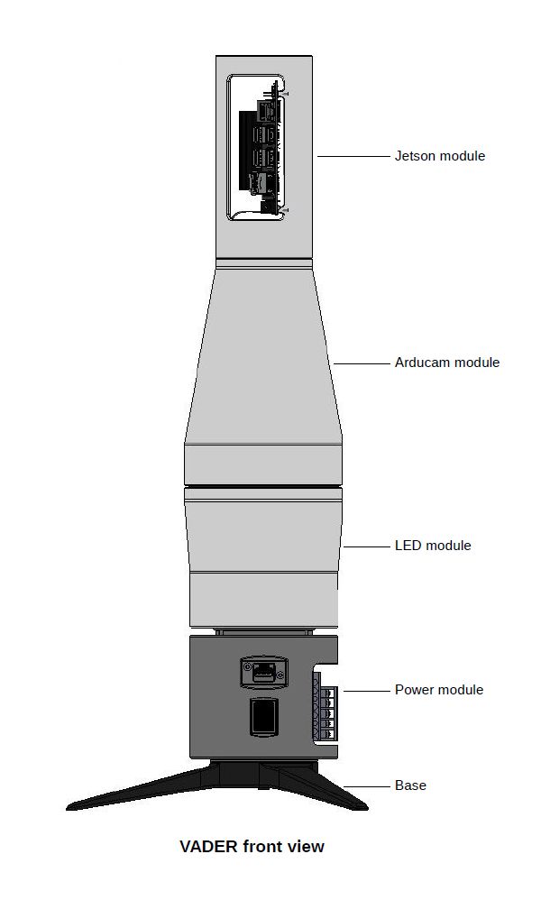
The complete VADER device consists of five subassemblies. Those five subassemblies come together into two major halves - upper one that does image processing, and lower one which provides stable base, power and place to put Petri dishes.
Five points below describe parts of the VADER device, from top to bottom.
Point 1.
Computer assembly with Jetson Nano SBC. This part simply helps keep Jetson Nano secure and with reasonable access to airflow for cooling purposes. Computer and camera assemblies are joined together using one hex screw going right through the bottom centre of the computer assembly. During assembly take care not to use too long mounting screw. It is possible to accidentally cause irreversible damage to a camera board with a screw that’s just one or two millimeters oversized.
Point 2.
Camera assembly with Arducam module - keeps the camera steady and at a fixed distance from Petri dish surface. Conical, totally enclosed shape of this part also helps prevent light ingress to ensure that lighting conditions remain the same between each photograph. As mentioned before, this part is mated together with computer assembly. Both of them create an upper half of the VADER device.
Point 3.
Backlight assembly (also used as Petri dish holder) is another essential part of the device. This is where optimal lighting conditions are created.
This part consists of external housing with a matte glass plate on the top. Matte glass is used because of its light-diffusing properties. This is also the place to put adjustable centering rings (depending on which size Petri dish is used). Glass light diffuser is easily removable in case the light sources at the bottom need replacement.
On the bottom part of a backlight assembly there is a circular housing for six G4 lamp sockets. The prototype uses jellybean GOOBAY-HE04-150 lampholders. Even though there is a space for six lamps, during testing it was determined that only three GOOBAY-30584 LED modules are enough to create proper lighting conditions.
Warning: the prototype device was designed only for LED light sources. Use of halogen light bulbs may create enough heat to damage plastic parts.
Assembling the light housing ring is pretty straightforward. Just mount the sockets, ensure they’re tight fit and solder the cabling. You should create a simple parallel connection. When done correctly, there should be very little wiring left and only two wires coming out of the light ring part. Take care not to create any short circuits. Make sure that wires are laid out in the right order. You should definitely avoid creating a “rats nest” situation with wiring - that may prevent you from properly connecting the light ring to backlight assembly housing.
Point 4.
Power supply assembly - a pretty simple part housing just two MeanWell fixed-voltage power supply units. A 5V PSU powering Jetson Nano SBC and a 12V PSU used to power the light ring with LED light sources.
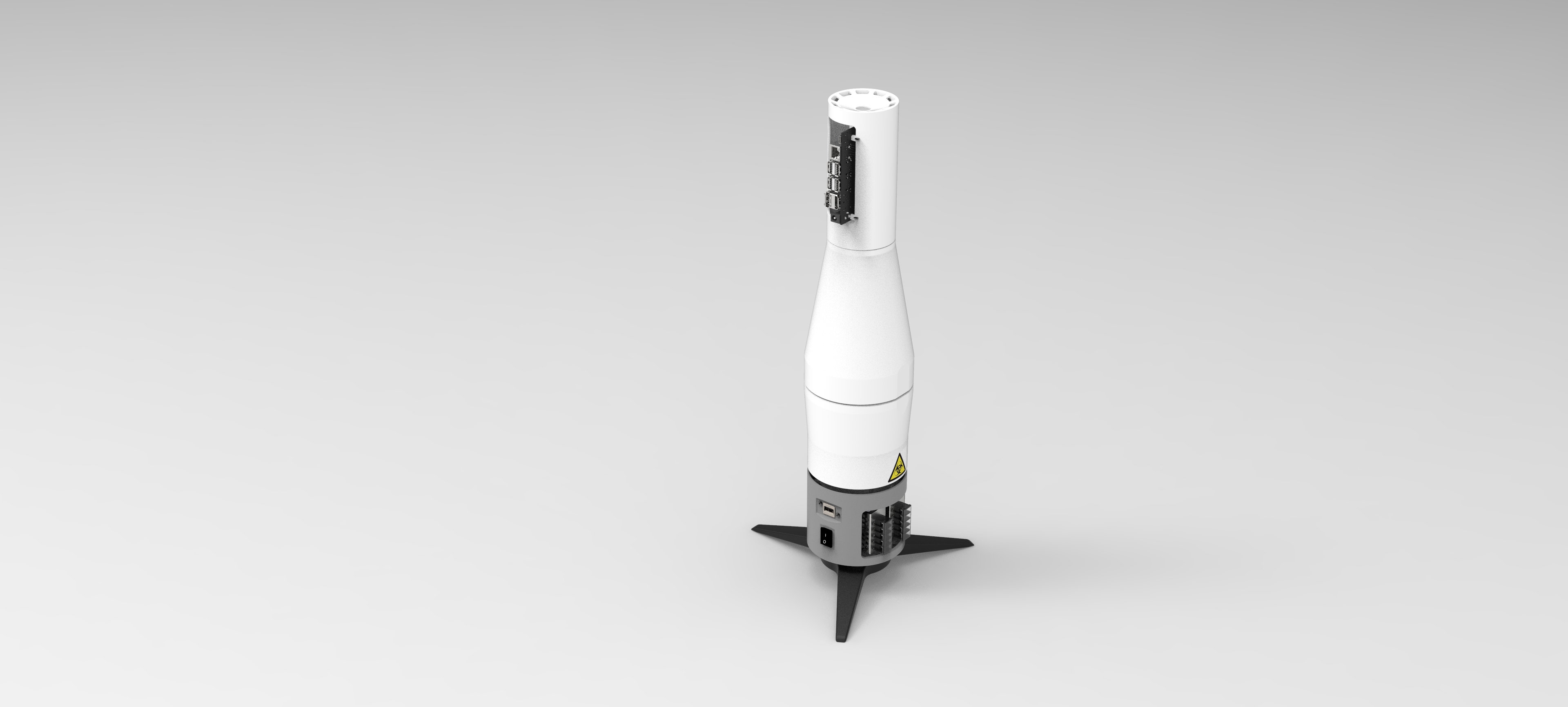
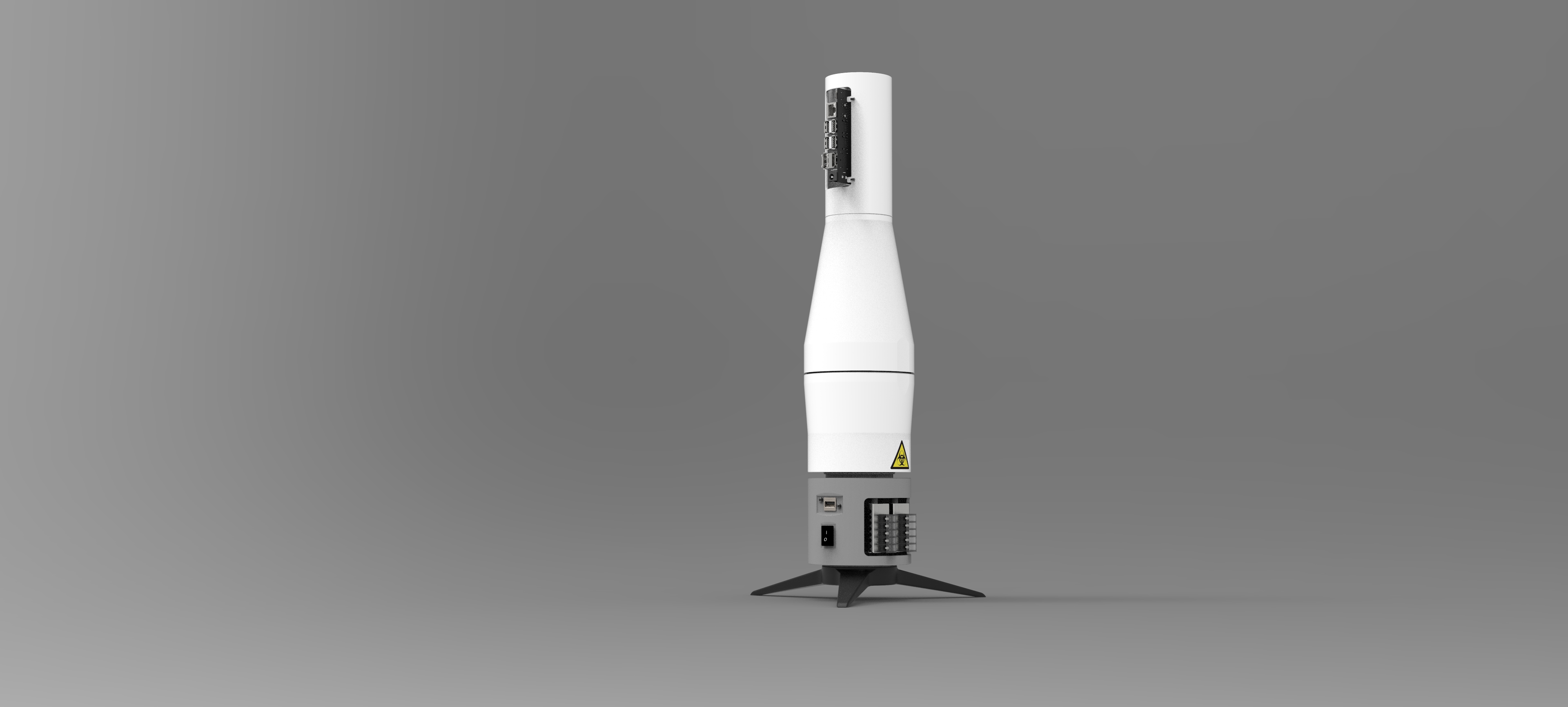
On the side of this assembly there is an USB socket (wired only for power delivery) and switch to disable LED lamps. Jetson Nano is powered with what could be called an overengineered phone charger (MeanWell PSU with USB socket). This is, however, a conscious decision. It is known that Jetson SBC, especially when under load, may require higher currents than those available from standard phone chargers.
Proper wiring and assembly of this part is essential to electrical safety of the entire device. Mains wiring is used here. If you are not comfortable with assembling mains-powered devices, seek advice from a qualified electrician. Failure to observe proper working practices here may result in hazardous conditions that create a risk of electric shock.
Make sure to put plastic covers on screw terminals of power supplies.
Point 5.
Base assembly - just a simple tripod providing stable upright position. Attached to a power module. Three lower modules (backlight, power and base) create the bottom half of the VADER device.
Hardware setup
Step 1: Print 3D corpus
Modules were designed for SLS printing (Selective Laser Sintering) due to relatively high dimensional accuracy required by electronic components, and also for stability and rigidness. After receiving printouts you may need to correct holes for screws. Drill through or thread, where required. Before assembling everything take a good look at printed parts, understand how and in which order they come together. Take note of proper screw diameters and lengths to be used. After preliminary montage and adjusting, you can dye your printouts for improved aesthetics. This would also help prevent them from yellowing under UV radiation.
Step 2: Assembly
Start from the base and the power module. When wiring everything together use stranded wire, the preferable cross section is 0.75mm2 (20 AWG). Solder wires to the LED switch and the USB socket. Mount them on a side wall of the power module. Mount both power supplies with M3x20 screws and, according to electrical diagram, connect wires to proper terminals. Connect the power cord. Ensure that two 12V wires come out of a rectangular hole on the top surface of a module.
Prepare the LED module. Assemble LED sockets on their plate, solder their wires together and route them through a rectangular hole in the bottom of a module. Screw a plate inside a module with three M3x18 screws. Join both modules with a central M5x16 screw.
Mount Arducam inside the Arducam module. Join Arducam module with Jetson Nano module using central M5x16 screw. Connect camera to Jetson Nano using CSI ribbon. Mount Jetson inside its module using four M2.5x8 screws.
Check circuit with the diagram. Check the reliability of all connections. Before first power-up check if there are no short circuits and, most importantly, if the mains wiring is done right.
Step 3: Bring it to life
1. Connect Jetson Nano to USB power socket via standard USB cable.
2. Connect HDMI, Ethernet, keyboard or mouse, if needed.
3. Insert power plug to wall socket. Jetson Nano should be powered.
4. Switch on the light to check if it works properly.
Software setup
Step 1: Install NVIDIA L4T and NVIDIA JetPack SDK [Jetson]
At the beginning your Jetson Nano and memory card are empty so you need to install a dedicated operating system (OS) from the Image file. Installation of NVIDIA L4T operating system and NVIDIA JetPack SDK 4.3+ was described here: https://developer.nvidia.com/embedded/jetpack
Key features in JetPack used by VADER: OS, CUDA, Computer Vision
Other steps were presented on the attached Jupyter Notebook. Feel free to analyse descriptions and code base at the same time.
Step 2: Collect, annotate and split data [GPU server]
Data preprocessing and training/evaluation model we recommend to do on external server which supports GPU computation. You can use Google Colab if you need a free access virtual machine with GPU.
Petri dishes images with phages colonies were crawled from the open data websites and collected from the friendly universities. To collect your own corpus we suggest to start with Actinobacteriophage Database at PhagesDB.org API (DOI: 10.1093/bioinformatics/btw711).
Each image with spots was annotated by hand using VGG Image Annotator (VIA) open-source tool and at the end exported to CSV file. The CSV export from VGG tool needs to be pre-processed by our custom Python code, before we use it for the next step.
Follow-up, samples from the pre-processed CSV file should be splitted into train/test and validation sets (separated CSV files). We recommend 70% / 20% / 10% proportions - but it can also depend on the number of available samples.
Step 3: Install Python scientific environment [GPU server/Jetson]
Install system packages and Python 3.6+ scientific environment on GPU server as well as on NVIDIA Jetson Nano. Installation details were included into Jupyter Notebook vader.ipynb.
We recommend to use SSH protocol for it:
scp vader.ipynb <username>@<IP_address>:/home/<username>

ssh <username>@<IP_address>

cd /home/<username>

sudo apt-get update
sudo apt-get upgrade
sudo apt-get install libatlas-base-dev gfortran libhdf5-serial-dev hdf5-tools libfreetype6-dev python3-pip
sudo pip3 install virtualenv

mkdir vader

mv vader.ipynb vader

cd vader

virtualenv -p python3.6 env
source env/bin/activate
Step 4: Train and evaluate your model [GPU server]
keras-retinanet Python package is a Keras framework implementation of RetinaNet object detection which is delivering two scripts:
- retinanet-train - to launch model training and evaluation
- retinanet-convert-model - to convert a training model to inference model (read more)
retinanet-train  --backbone vgg16 --weights snap_vgg/vgg16_csv_10.h5 --steps 60 --random-transform --epochs 10 --batch-size 1 --snapshot-path snapshots_vgg_new/ --gpu 0 --freeze-backbone  --tensorboard-dir tb_vgg_new/ csv dataset/vader_train.csv dataset/classes.csv > train_vgg_new.out &

retinanet-convert-model snapshots/best_snapshot_name.h5 out/vader_model_vgg.h5
The training and evaluation sessions live can be observed by Tensorboard Python package. This library allows you to launch web browser application available on your GPU server (<IP_adress>:8889).
tensorboard --logdir tb_vgg/ --port 8889You can stop training by breaking the process or it will stop by itself after a specific number of epochs. This case shows that after 6 epochs we achieved an accurate model.
Final model was saved as vader_model_vgg.h5 file.
Step 5: Deploy model on Jetson Nano [Jetson]
Final model vader_model_vgg.h5 needs to be moved from GPU server to NVIDIA Jetson Nano. To make it happen once again use SSH protocol:
scp vader_model_vgg.h5 <username>@<IP_address>:/home/<username>/vaderNext, log in to NVIDIA Jetson Nano, activate Python scientific environment and launch Jupyter Notebook (Lab) application.
ssh <username>@<IP_address>

cd /home/<username>/vader

source env/bin/activate

jupyter lab --port=8888 --no-browser --ip=0.0.0.0 --NotebookApp.token='' --NotebookApp.password=''
Go to the web browser and put <IP_address>:8888 address as URL. Then you will see the Jupyter Dashboard which allows you to select and launch vader.ipynb notebook file.
From the vader.ipynb notebook view you can make a picture with gst-launch-1.0 application for putted Petri Dish and finally execute spots detection procedure as well as extract more meta information from classification process.
Step 6: Demo [Jetson]
gst-launch-1.0 is a tool that builds and runs basic GStreamer pipelines. We're using it to take pictures with the Jetson and our camera system.
gst-launch-1.0 nvarguscamerasrc do-timestamp=true num-buffers=30 ! 'video/x-raw(memory:NVMM), width=(int)3280, height=(int)2464, framerate=(fraction)21/1' ! nvvidconv ! jpegenc ! multifilesink location=image/test_vader.jpegAfter that, load the best model and classify the picture from gst-launch-1.0.
# Import custom vader modules
from vader import VaderModelLoader, VaderDetector
# Load final model
model = VaderModelLoader(
    model_path='vader_model_vgg.h5'
).load_model()
# Prepare detector instance
detector = VaderDetector(model)
# Detect spots with 0.9 treshold
# and save classification results into "detected_test_vader.jpg" file
detector.detect(
    image_path='image/test_vader.jpeg',
    score_th=0.9,
    output_path='detected_test_vader.jpg',
    resize=True,
    crop=True
)VADER device is pretty safe to handle, even during the early prototyping stage. There are no mechanically moving parts that could pose any hazard to limbs, sight or hearing. Nor there are any hazardous substances used during operation. The only risk is related to electrical wiring.
The device is powered with 230V mains voltage. General rules for working with mains voltage apply:
- First and foremost - if you're doing any changes to wiring (mains or low voltage), remove plug from socket first. Make sure the device is not powered.
- When doing the assembly you should be familiar and comfortable working with mains voltage connections. You should have no trouble understanding and differentiating between live, neutral and earth wires. If you feel you’re not sure about your electrical work - ask a qualified professional for help. This is not a toy, improperly wired mains voltage can be lethal so be careful.
- When stripping wires, both for mains cabling and for low-voltage parts of the circuit make sure you don’t cause unwanted damage to wire insulation. Damaged mains insulation may cause electrical breakdown and shock hazard. Also, take care not to nick the actual wire. Loss of wire cross section may cause an increase in resistance, unwanted heating and possibly fire.
- Keep your wiring neat and tidy, it helps prevent hazards and accidents.
Other important things to mind while doing any work on VADER:
- Electronic devices - that is NVIDIA Jetson SBC and attached camera module - are very sensitive to static discharge. You should observe proper working practices for dealing with static-sensitive circuits. Damage by static electricity may not be obvious, may not be total and may cost you lots of time wasted in debugging. Two most important rules of thumb are:
- Don’t wear synthetic clothing while doing assembly work.
- Hold boards by their edges. Avoid touching actual circuits, connectors or integrated circuits.
- While mounting boards to plastic housing take care not to damage electronic circuits with screws or screwdrivers. Subtle damage on a single track may be just enough to stop your NVIDIA Jetson board from operating properly.
- This is a proof of concept and early prototype. Do not use it with materials or Petri dishes that may cause an actual biological hazard. This device is not designed to be fully disinfected.
- Heatsink mounted on NVIDIA Jetson SBC may get hot. While there is no risk of receiving burns, it may cause you to do sudden, instinctive movements of hand. This in turn may cause damage to plastic parts of the prototype. Take care while checking the temperature and use the outer side of your hand.
- When soldering make sure that your joints are done properly (that is there are no “cold solder joints”). Use a proper-size and power soldering iron to get wire joints to a correct temperature. Use of additional rosin flux may be recommended. When soldering, mind the time heat is applied to a joint - too long and you may melt the insulation on wires.
- Stay focused, learn, improve and enjoy :)


Piotr Tynecki
Wojciech Głażewski


Comments