
Like an Arduino Nano just enough circuit to get you going. We need to program through the SWIM interface pins until we add a bootloader to program on USB. More on theboard.
Contains the STM8S103 or STM8S003 MCU microcontroller unit from Thompson Semiconductor corporation. We will see long lists of chip numbers but these chips all have 1kB RAM and 8kB flash memory for programs. An 8bit processor comparable to an ATtiny or 8051 chip.
The boards are listed as STM8S003F3P6, STM8S103F3 and STM8S103K3T6. Specifications are the same, programs compile same for both. LED pin B5 for the little board and pin C3 for the big one.
SWIM Programming InterfaceTo upload your compiled binary executable program you need an ST-Link programmer device. We'll use an inexpensive ST-LinkV2. The SWIM pins are for STM8 and SWD is for other chips.
Look closely at the label printed on the programmer and the pins. Connect RST-SWIM-GND-3v3. You can power some boards from the ST-Link.
This is the design studio program provided to develop software for STM8 processors. We can open and manage a project workspace in assembly language but we will need to install a compiler program to compose our C/C++ projects.
Look at the menus. Open sub-menus to see what other commands are there. The build menu compiles our source files into executable programs for us. There are keyboard shortcuts.
STVD installed sample files that will run on your computer. Look for the extension .stw for STVD Workspace. Files for a software project can be organized anywhere in your computer. Defaults are in C:\Program files (x86)\STMicroelectronics.
Create New WorkspaceCreate a new folder named stm8asm that you can put the files into. Open STVD and create a new workspace named stm8asm. Menu File->Create Workspace name stm8asm and locate in the folder stm8asm that we created. Save the workspace.
New Project name stm8 and locate in the same folder stm8asm. This program suite is part of STVD and is from Thomson Semiconductor.
Select Toolchain ST Assembler Linker. Make sure that it finds ST Assembler Linker for the Toolchain root.
STVD includes files for many ST7 and STM8 processors. Select STM8S003F3P MicroController Unit. It works with the boards in the picture.
Save the workspace. If we setup right we should see new default files in our project folder. STVD automatically generates Source Files main.asm, mapping.asm and mapping.inc. You might see files used by STVD such as the workspace file stm8asm.stw.
We will work mostly with main.asm. This is a template program that compiles and uploads to a processor. It is grammatically correct but there is no action to be done.
This is a program that compiles and shows us we have a working toolchain. We are setup to program STM8 chips and we have code for it.
Expand the Source & Include Files folders and open the three text files. They are the same ones we saw in the folder. Right-click on icons and you will see extra commands that are on the menu bar. This is how we add and remove files and locate them by properties.
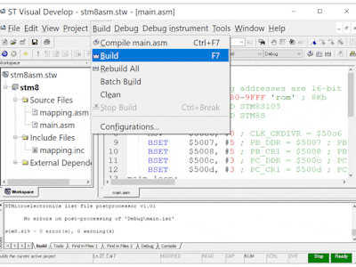
Build->BuildPress F7 on your keyboard or menu Build->Build and watch the text zip past at the bottom of the screen. We are watching the assembler and linker convert our source program into an executable.
A new file has been generated named stm8.s19. This extension means it is a Motorola format program file, like a hex file. The output shows us that our toolchain is healthy and working. Plus we see exactly what options are added to each command.
We Made a New File?STVD generated output files in our project folder. Look inside the new Debug folder. When you check menus look for this name.
In the Debug folder the file we care about is stm8.s19. Some of the other text files are maps and listings that you can open with notepad. Notice all were generated at the same time. The Build->Clean command erases all of these.
Open main.asm in the editor screen. Remove the default text and replace with our code from below or the attachment.
We could remove the files mapping.asm and mapping.inc they are not called by our blinky program.
CodeSelect all of the default code in the main.asm file and replace it with:
stm8/
	MOTOROLA
	WORDS		; following addresses are 16-bit length
	segment byte at 8080-9FFF 'rom'	; 8Kb
; PB5 for Small BOARD STM8S003F3P6
; PC3 for Big   BOARD STM8S103K3T6
.main
    MOV     $50c6, #0 ; CLK_CKDIVR = $50c6 clock value
    BSET    $5007, #5 ; PB_DDR = $5007 ; PB_DDR|=(1<<PB5)
    BSET    $5008, #5 ; PB_CR1 = $5008 ; PB_CR1|=(1<<PB5)
    BSET    $500c, #3 ; PC_DDR = $500c ; PC_DDR|=(1<<PC3)
    BSET    $500d, #3 ; PC_CR1 = $500d ; PC_CR1|=(1<<PC3)
main_loop:
    bcpl    $5005, #5 ; PB_ODR = $5005 ; PB_ODR^=(1<<PB5)
    bcpl    $500a, #3 ; PC_ODR = $500a ; PC_ODR^=(1<<PC3)
	call    	delay
    jp      main_loop
delay:
    ld 	    a, #$30 	; #$30 hex for 48 decimal
    ldw     y, #$d400 ; #$d400 hex 54272 decimal
loop:
    subw    y, #$01 	; decrement with set carry
    sbc     a, #0 		; decrement carry flag_flag
    jrne    loop
	ret
    end
Comment lines begin with semicolon ; and spaces vs tabs are important in this language. Be careful copying, pasting and editing. Compile frequently.
It is a basic program that toggles two IO pins on our STM8 board. It works for both of the units listed in our BOM bill of materials.
Change value of a or y to get a longer or shorter delay. Tabs are important in assembly syntax.
Build->BuildTurns our main.asm into an .s19 file using the asm command. The clean command erases all of our output and leaves our source files.
The default is to create a file in the debug folder. Looks a lot like Intel hex file.
We often call these software loads firmware. The idea is that we are putting software into a solid device. Program STM8S Processors with ST-Link SWIM Interface shows how to connect our development board to the PC.
Menu File->Open and navigate to the debug folder inside the cosmic directory located somewhere on your computer. You can filter to see .hex, .s19 or all files.
The numbers on the screen are the ones and zeros of our firmware.
Program->Current tabWatch text scroll at the bottom to show progress. I have to exit for my board to restart.
Change value of a or y to get a longer or shorter delay. Tabs are important in assembly syntax. LED pin B5 for the little board and pin C3 for the big one.


Comments