


Hardware components | ||||||
 |
| × | 1 | |||
_ztBMuBhMHo.jpg?auto=compress%2Cformat&w=48&h=48&fit=fill&bg=ffffff) |
| × | 1 | |||
 |
| × | 1 | |||
| × | 1 | ||||
 |
| × | 1 | |||
1. Connect WS2812B Modules:
- Connect the data input (DI) of each WS2812B module to a digital pin on the Arduino (e.g., pin 6).
- Connect the 5V and GND pins of the WS2812B modules to the 5V and GND pins on the Arduino, respectively.
2. Power Supply:
Connect a 5V power supply to the 5V and GND pins on the Arduino and the breadboard.
Programming:
Write a program for the Arduino that utilizes the Adafruit NeoPixel library to control the WS2812B modules and create various lighting patterns on the LED matrix display.
Example code for displaying a rainbow pattern:
#include <Adafruit_NeoPixel.h>
#define LED_PIN 6
#define NUM_LEDS 64 // Change this to match the number of LEDs in your matrix
Adafruit_NeoPixel matrix = Adafruit_NeoPixel(NUM_LEDS, LED_PIN, NEO_GRB + NEO_KHZ800);
void setup() {
matrix.begin();
matrix.show(); // Initialize all pixels to 'off'
}
void loop() {
rainbowCycle(20); // Display rainbow cycle with 20ms delay per step
}
void rainbowCycle(uint8_t wait) {
uint16_t i, j;
for(j=0; j<256*5; j++) { // 5 cycles of all colors on wheel
for(i=0; i<matrix.numPixels(); i++) {
matrix.setPixelColor(i, Wheel(((i * 256 / matrix.numPixels()) + j) & 255));
}
matrix.show();
delay(wait);
}
}
uint32_t Wheel(byte WheelPos) {
if(WheelPos < 85) {
return matrix.Color(WheelPos * 3, 255 - WheelPos * 3, 0);
} else if(WheelPos < 170) {
WheelPos -= 85;
return matrix.Color(255 - WheelPos * 3, 0, WheelPos * 3);
} else {
WheelPos -= 170;
return matrix.Color(0, WheelPos * 3, 255 - WheelPos * 3);
}
}
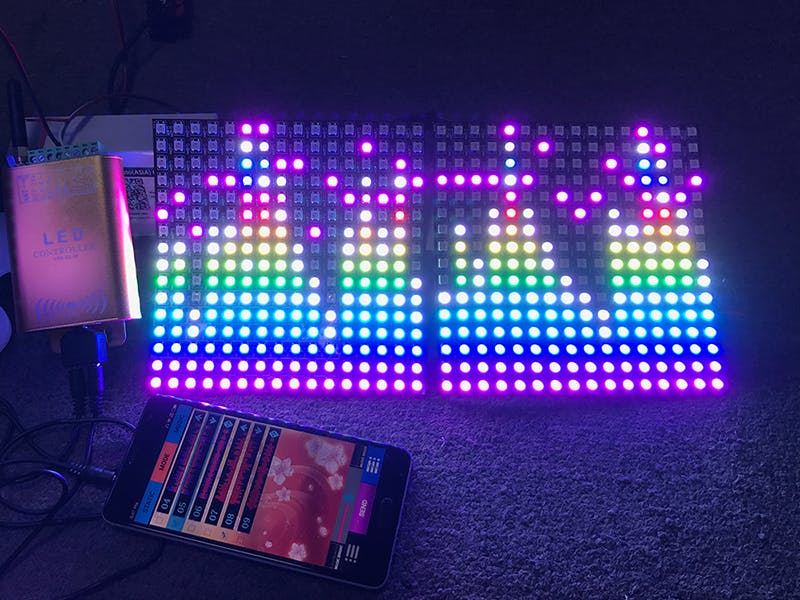
Testing:
Upload the program to the Arduino and power up the circuit. The LED matrix display should show a colorful rainbow pattern cycling through the LEDs. Adjust the code and experiment with different patterns and colors.
ConclusionBuilding a colorful LED matrix display with WS2812B modules allows for creating dynamic lighting effects and visual displays. This project demonstrates the use of WS2812B in creating a custom LED matrix and provides a foundation for creating interactive lighting projects.


_3u05Tpwasz.png?auto=compress%2Cformat&w=40&h=40&fit=fillmax&bg=fff&dpr=2)
Comments