


Hardware components | ||||||
 |
| × | 1 | |||
 |
| × | 1 | |||
 |
| × | 1 | |||
 |
| × | 1 | |||
 |
| × | 1 | |||
| × | 1 | ||||
Software apps and online services | ||||||
| ||||||
 |
| |||||
This is a project for beginners looking to get started with Internet of Things (IoT) and Sensors.
The aim of the project is to make a simple Humidity and Temperature Tracker that you can monitor from your phone.
MOTIVATIONAs a beginner in electronics, I was really excited to work on this project as it gave me the opportunity to understand better how to use IoT (specifically with Blynk and the Esp32) and Sensors (it is my first time using a digital sensor). After battling various hurdles to bring this supposedly simple project to life, I decided it would be good to post a guide for other beginners to make use of and profit from without as much hassle. I hope you enjoy it!
I would like to give a shout out to Pius Ndukwu for his mentorship and advise.
OUTLINESTEP 1: Add and Install necessary libraries and board in your Arduino IDE
STEP 2: Make the connections on the breadboard
STEP 3: Set up the code in the Arduino IDE
STEP 4: Setting up Blynk
STEP 5: Uploading code to the esp32
STEP 6: Monitoring from the Blynk app on your phone
STEP 1: Add and Install necessary libraries and board in your Arduino IDETo add the esp32 board, you need to go to File > Preferences then click on the green button towards the right of the "Additional boards manager URLs" bar
Then click on the "Click for a list of unofficial board support URLs" link
It will open up the github website on your browser. Scroll down to "Espressif ESP32" and copy the URL there. Go back to the Arduino IDE and paste it there then click on the "OK" button
You also need to go to Tools > Board > Boards Manager (or press Ctrl + Shift + B) then search esp32 and click on install (which will be where the remove button is showing in the image below)
For the DHT Sensor, go to Sketch > Include Library > Manage Libraries (or Ctrl +Shift + I) and download the following libraries:
For Blynk, go to Sketch > Include Library > Manage Libraries (or Ctrl +Shift + I) and download the following libraries:
Connect the components together as shown in the fritzing circuit diagram below. The connections are also explained below.
The DHT11 (Digital Humidity and Temperature Sensor) has four pins namely(from left to right):
1. VCC (Power supply 3.3 to 5.5 Volt DC)
2. DATA (Digital output pin)
3. NC (Not in use/not connected)
4. GND (Ground)
Connect the VCC pin of the DHT11 to the VIN pin of the esp32.
Connect the DATA pin of the DHT11 to the D26 pin of the esp32.
Connect the GND pin of the DHT11 to the GND pin of the esp32.
Connect the 10K Ohm resistor between the VCC and DATA pin of the DHT11.
STEP 3: Set up the code in the Arduino IDEThe code has been uploaded in the attachment section. You can go there and copy it then paste it in your Arduino IDE. The code is commented so you can use the comments to follow along with what is happening and know what else you need to do to fully set up the code. I will be explaining the code here also for those who may prefer that.
The Blynk and Wi-Fi connection setup section
Lines 3 to 5 define constants for the Blynk Template ID, Blynk Template Name and the Blynk Authorization Token.
The code in line 6 is to print the Blynk connection status to the serial monitor.
Lines 8 and 9 are to include the libraries that will enable the esp32 Wi-Fi module be connected to Wi-Fi.
Line 10 is to include the library that allows basic Blynk Functionalities for the esp32
Line 13 is creating a character array to store the Blynk Authorization Token.
Line 16 and 17 are to create character arrays to store your Wi-Fi SSID and password i.e. the Wi-Fi SSID and password that the esp32 will connect to. You are to replace the text between the double quotations with your actual Wi-Fi SSID and password.
The DHT11 setup section
Line 19 is including the DHT library to make use of the library functionalities like creating DHT objects and using the methods.
Line 21 is defining the pin of the esp32 that the DATA pin of the DHT11 is connected to i.e. 26.
Line 23 is defining the type of Digital Humidity and Temperature Sensor i.e DHT11.
Line 25 is making an object (myDHT) of the DHT class and inputting arguments for the constructor method namely the DHTPIN and the DHTTYPE
The VoidSetup Function
Line 28 begins the serial monitor and sets the baud rate to 9600.
Line 29 delays for 1.5 seconds to allow the serial monitor fully set up before printing out the text on line 30 to avoid double printing
Line 32 sets up Blynk connection by inputting the various necessary arguments
Line 35 begins the object created for my Sensor i.e myDHT.
The Void Loop Function
Line 39 delays for 2 seconds to avoid the humidity and temperature values printing too fast to the serial monitor and Blynk app.
Lines 40 and 41 use readHumidity and readTemperature methods to get humidity and temperature values respectively which are both then stored in float variables.
The if statement from line 44 to line 48 checks whether the DHT sensor read both values if not it returns to attempt to read values again.
Line 50 is running the set up Blynk to be able to output values to the Blynk app.
Lines 52 and 53 are writing the humidity and temperature values to the first virtual pin (V1) and second virtual pin(V2) respectively.
Lines 56 to 61 are outputting the values of humidity and temperature to the serial monitor so that you can track values from there and check for errors.
STEP 4: Setting up BlynkGo to https://ny3.blynk.cloud/dashboard/login on your PC or Desktop and login in to your Blynk account. If you do not have a Blynk account, click on the "Create new account" and sign up.
Click on "Developer Zone" and then on the "New Template" button (at the top right).
Create a name for your template in the "NAME" slot then set your "HARDWARE" to "ESP32" (or whatever ESP board you are using) and the "CONNECTION TYPE" to "Wi-Fi" and click on done.
Click on the "Datastreams" tab and click on the "New Datastream" button
Then click on Virtual Pin
The Virtual Pin Datastream interface pops up. Set the "NAME" to "Humidity". Set the "PIN" to "V1". Set the "DATA TYPE" to "Double". Set the "UNITS" to "Percentage, %". Set the "MIN" and "MAX" to "0" and "100" respectively and set the "DEFAULT VALUE" to "0." Once done, click on the "Create" button at the bottom right.
Click on the "New Datastream" button now towards the top right and click on "Virtual Pin."
Set up the new Virtual Pin Datastream for Temperature similarly to the one for Humidity with the only differences being in the NAME, PIN and UNITS which will be "Temperature", "V2" and "Celsius, °C" respectively.
Click on the "Save" button towards the top right of the screen.
Click on the "Devices" button below the Developer Zone button. (The buttons should be on the left side of your screen) then click on the "New Device button" which should be towards the top right of your screen.
Then click on the "From Template" option.
Choose your current Template and name your device then click on the "Create" button.
Copy to your clipboard the New Device info at the top right of your screen and replace line 3 to line 5 of your Arduino IDE code with the copied information.
Go to the app store or play store and download the "Blynk IoT" app. Open the app and click on the "Log In" button then type in your email and password and log in.
Click on the device you created on the Blynk website.
Click the wrench icon then the "+" button towards the bottom. Scroll down and click on the "Value Display" widget. Create this widget twice (one will be for humidity while the other would be for temperature).
Click on the first value display and then the "Choose Datastream" slot then select Humidity(V1).
Click the Design button towards the bottom right and Enter the title as "Humidity:" then set the font size to your preferred font size then go back once. Click on the second value display widget, choose the datastream as Temperature(V2) and then go to design and enter the title as "Temperature:" then set the font size and go back twice.
You have successfully created your phone monitor dashboard. Congratulations! It should look like this.
Connect the esp32 to your pc using a Type C cord and select your board in your Arduino IDE from Tools > Board > esp32 > ESP32 Dev Module (or whatever your board is) and port from Tools > Port > COM3 (or whatever your port is).
Open your serial monitor with the button in the Arduino IDE at the top right.
Click the "Upload" button or Ctrl + U and wait for the code to compile and get uploaded.
Once the code has been uploaded, check to serial monitor to confirm that the esp32 has successfully connected to Wi-Fi and then the DHT11 Sensor is sensing Humidity and Temperature and printing them out to the Serial Monitor. If you encounter any problems, ensure the connections are secure that the DHT11 sensor and esp32 board don't have any visible faults. If the problem persists, try changing the pin you are connecting the DATA pin of the DHT11 to i.e. from D26 to another pin (Remember to change the defined DHTPIN in your code to the esp32 pin number you have now connected it to).
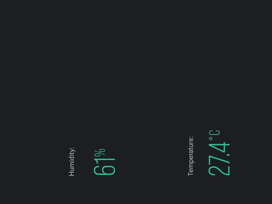
STEP 6: Monitoring from the Blynk app on your phoneOnce all issues have been resolved and the esp32 is confirmed to be online, then open up the Blynk App on your phone and click on the device you created and monitor the Humidity and Temperature readings from there. It should look like this
If it does then congratulations, you have successfully created the Humidity and Temperature Monitor!
If you followed this tutorial fully then you have gained some basic skills in IoT and Sensors. Well done on completing the project!
Monitoring Humidity and Temperature from your phone! (Blynk) Fritzing Circuit Connection Diagram
I made use of the white DHT sensor because I could not find the DHT11 component (blue) but the connection is still the same.
The resistor is a 10k Ohm Resistor.
humidity_sensor_connection_diagram_bb_12KETyPNgQ.png)


humidity_sensor_connection_diagram_bb_12KETyPNgQ.png)
Comments