

Hardware components | ||||||
 |
| × | 1 | |||
| × | 1 | ||||
 |
| × | 1 | |||
 |
| × | 1 | |||
 |
| × | 1 | |||
 |
| × | 1 | |||
 |
| × | 1 | |||
 |
| × | 1 | |||
 |
| × | 10 | |||
Software apps and online services | ||||||
| ||||||
From my observation, most proximity sensor systems installed in cars make use of audio cues, such as high-pitch beeps, to inform the driver of the proximity of the car to physical obstacles. However, apart from cars equipped with cameras at the back, there are no other forms of indicators that use visual cues.
Furthermore, when it comes to flying drones or controlling RC vehicles, there may be no visual indicator for the user to know how close the gadgets are to physical obstacles, as cameras on these gadgets can only point in one direction at any given moment.
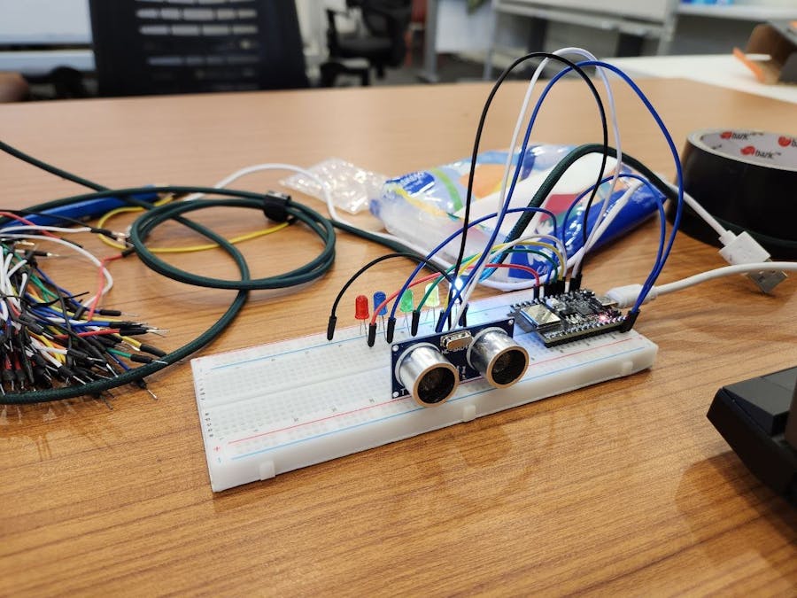
The idea was to create a simple proximity sensor, using the Arduino ESP32, Firebase real-time database, Ultrasonic sensor, and LED lightbulbs. In real-life applications, the Ultrasonic sensors, ESP32 will be on the vehicles, detecting and relaying information on proximity through Firebase, which will send data over to the remote control devices with the light indicators. For motor vehicles, the system will be integrated within the car itself.
Basic Specifications:Input voltage: 5V
Included library: WiFiMulti, ESP32Firebase, WiFi
Before utilizing the ESP32 with Firebase and an ultrasonic sensor, ensure you have the necessary libraries installed. Download and extract the specific library files, then add them to your Arduino IDE's library folder.
Before programming your ESP32, it's crucial to set up a Firebase Realtime Database. This involves creating a Firebase project and obtaining your database URL and authentication credentials. Once configured, incorporate the Firebase library in your development environment to enable your ESP32 to communicate with the Firebase database. This setup facilitates data storage and retrieval, allowing real-time interaction between your ESP32 device and the cloud for dynamic control and monitoring applications.
After restarting the IDE, your environment will be ready to handle the ESP32's commands for WiFi connectivity, Firebase interaction, and sensor data handling. Follow the tutorial for detailed instructions on wiring and code compilation to avoid errors and ensure proper device setup for real-time data monitoring and control.
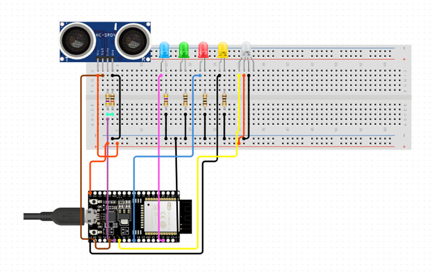
Pin Wiring to ESP32UltrasonicTRIG----------------------PIN18
ECHO---------------------- PIN 19
GND-----------------------GND
5V------------------------5V
LEDRed------------------------PIN 8
Blue------------------------PIN 7
Green------------------------PIN 6
Yellow------------------------PIN 5
White------------------------PIN 4
5V------------------------5V
Reading data from an ultrasonic sensorTo gather data from the ultrasonic sensor, initially ensure the ESP32 setup is correctly completed.
Navigate to the appropriate example within your development environment to load the foundational code.
After successful upload, launch the serial monitor to observe output data. Bring the sensor into proximity with the target object, maintaining a close distance to accurately capture and display all relevant measurements and information on the serial monitor.


Comments