


Hardware components | ||||||
| × | 1 | ||||
| × | 1 | ||||
| × | 1 | ||||
Hand tools and fabrication machines | ||||||
 |
| |||||
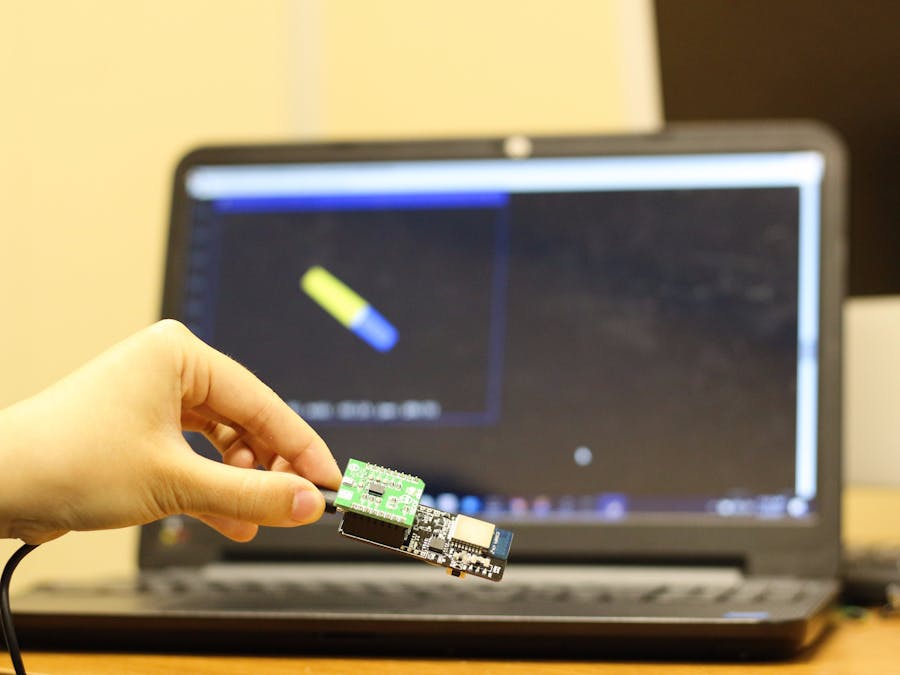
This is a beginner level project aimed to demonstrate the use of the CC264BPA-RUNN Runner board along with the mikroBUS 10DOF Click board to create a real-time 3D visualization of the board. In this project you will be creating a Python script that will project a block that moves according to the readings of the Roll, Pitch, and Yaw values from the IMU. Isn't that neat?!
This is a two part project:
In part one we will use a Windows PC connected to the runner board using a USB cable, and in part two we will use a Raspberry Pi3 that has Bluetooth BLE capabilities to connect to the runner board.
I will link Part 2 once it is up!
Before starting, I would like to briefly explain about the two boards that we will be working with!
Hardware ComponentsCC264BPA-RUNN
In this project we will be using the GT-tronics' CC264BPA-RUNN Runner board. CC264BPA-RUNN Runner is a prototyping board powered by Texas Instruments CC2640 wireless SoC and it can interface I2C devices (i.e. IMU). The Runner board can be plugged into a PC/MAC/UNIX or any machine with a USB host. Or it can be wirelessly connected to a Bluetooth BLE capable host such as the later version of iPhone/Android or Pi0w/3.
Unlike using an Arduino or other MCU boards, CC264BPA-RUNN Runner comes with firmware which allows users to access generic I2C devices, and the programming can be done completely on the host side (connected through USB or BLE) using AT commands.
This Runner board can be powered in two ways - through USB, or using a coin battery. It is also easily compatible with many click boards of choice. In addition there are Python support files that comes along with this board to enable the communication.
You may explore more on the AT-Commands and the capabilities of the firmware (DataExchanger) via their github link:
https://github.com/GT-tronics/dataexchanger-sample-codes
mikroBUS 10DOF Click Board
The mikroBUS 10DOF Click board from MikroElektronika contains 2 Bosch IC chips: a BNO055 9 axis absolute orientation sensor and a BMP180 barometer (digital pressure sensor). In this project, we will focus on BNO055 only.
BNO055 can produce accurate 9DoF readings of the accelerometer, magnetometer, and the gyroscope. Along with that, this chip is capable of providing sensor fusion measurements which allows you to read the quaternion/ Euler angles without implementing any algorithms.
Assembly:This step is as easy as…...
1) Solder the female headers that comes with the package to the right and left sides ensuring that the pin header is aligned to the end of the board, as shown below.
2) Attach the 10DoF clickboard onto the runner in the correct orientation.
3) Connect the Runner board to the PC using the micro USB cable. Ensure that the power switch is on USB and not BAT, otherwise it will use the power from your battery.
And now you are all set up to get the code running!
Let's Code!1) Make sure you have Python3 installed in your Windows PC, if you don’t refer to:
https://www.python.org/downloads/
2) Once you have that installed, be sure to have PyGame and also PyOpenGl installed on your PC. The PyGame library allows you to create game applications that access sound/graphics libraries, and PyOpenGl is used for all the graphics in this application.
If you don’t have these two libraries installed, open up your Command Prompt and type in the commands:
pip install PyGame
and
pip install PyOpenGl
3) Clone the Github project file linked below.
4) Open up imu2 in a text editor
In this script, there are three ways that the BNO055 takes measurements to produce the imaging:
- Euler angles [fusion algorithm done by BNO055]
- Quaternion Angles [fusion algorithm done by BNO055]
- Raw data [translated from Free IMU library https://github.com/femtoduino/imuduino-btle/blob/master/Arduino/libraries/FreeIMU/FreeIMU.cpp ]
At the top of the code, there are a set of instructions that you can follow to see which areas you need to comment out according to the angle calculation method you choose.
At default the code is set to read data from the 9 axis readings.
Now, I will be highlighting the important pieces of code in this section to clarify some things!
1) In the Initiation section, the AT command that we use mostly is :
At+ I2CRW=0,0x280,___
I2C is the communication protocol we are using. The I2C bus allows the runner (master) to communicate with the click board (slave). AT+I2CRW is the read and write command that can write into the different registers, and retrieve back the input.
2) In the MyRead function , serial.read(n)
is called so that it can return the data after you write into the board. This function also includes a buffer that waits for the command to be completed indicated with (OK), and will return the values to the user.
This is how we retrieve the data we need for the angle measurements.
Further explanations are commented within the code.
5) To run this code, use command prompt to navigate to the saved folder and then type in:
python imu2.py
In the application, you may press Z to turn on the YAW mode (Z axis reading), and hit ESC when you want to close application.
Be sure to lay the runner board flat on the table until initiation is complete. Once the lines of OK are printed, you may move the board.
Now play around with the three different ways you can read the chip- Euler/Quaternion/Raw Values
And Voila- You are now done Part 1! Part two will be coming up shortly to make everything here work wireless!

Sara Cheng

Ming Leung


Comments