


Hardware components | ||||||
 |
| × | 1 | |||
| × | 1 | ||||
 |
| × | 1 | |||
| × | 2 | ||||
| × | 2 | ||||
 |
| × | 1 | |||
 |
| × | 1 | |||
| × | 1 | ||||
| × | 2 | ||||
Software apps and online services | ||||||
 |
| |||||
Hand tools and fabrication machines | ||||||
 |
| |||||
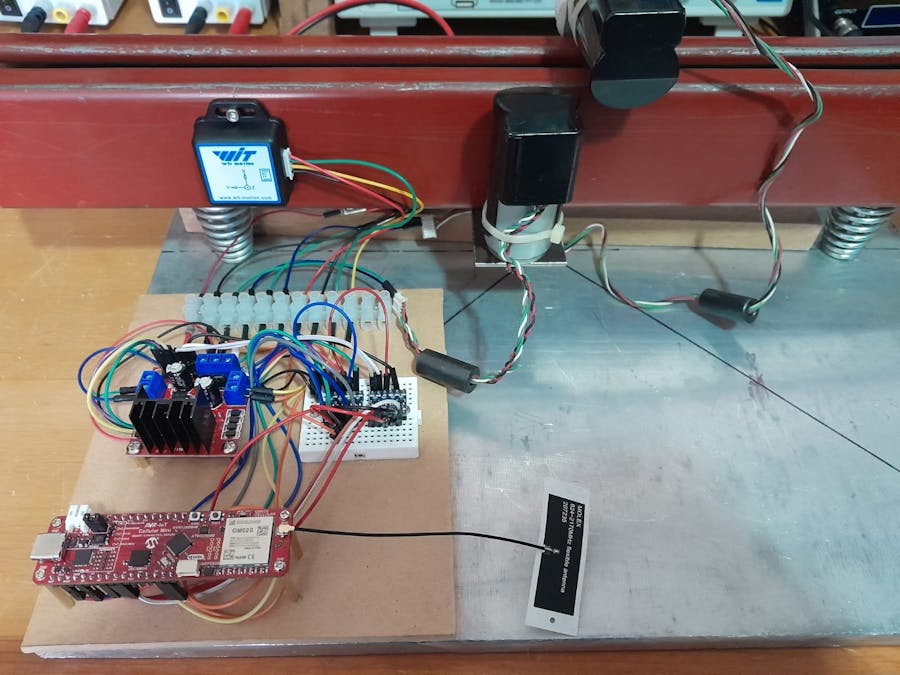
This project demonstrates how to build a hardware-based vibration device, for simulating the forces that are applied to curvature sections of rails in a suburban train line.
For simulating the forces exerted on the rail, two motors each with an eccentric piece placed on the rotor, are attached for creating vibration on each of the horizontal and vertical axes.
The device obtains the vibration data from an accelerometer and transmits to a web site for later analysis.
MotivationThe building of suburban train lines represent a challenge when they are developed in high density urban locations like Mexico City. Suburban train lines are very convenient for transporting many people; they are environmental friendly, tend to free roads of many cars and are a very good option for traveling among different living, working, touristic and commerce places in the city.
In Mexico City, we have underground, superficial and aerial (over columns) suburban train lines. In the aerial part of Line 12, there are train rails with high curvature sections, due to the complicated trace that runs among the streets, houses and buildings.
Vibration produced by the transit of trains over rails is a well-studied area. Nevertheless, it is interesting to develop a device for experimentation and self study of the phenomenon. Also, it could be convenient to send the vibration data over cellular networks, instead of WiFi, due to its inaccessibility along the train lines. Thus, it is a good idea to get experience with the AVR IoT Mini Cellular Board.
IoT Rail Vibration GeneratorThe device was built using recycled material for the main structure. The train rail is simulated using a section of steel profile obtained from a recycling warehouse. It is mounted over two conical steel springs, the longest diameter of the spring close to the rail, for better vibration. The rail and the springs are attached with long screws to an aluminum square plate.
The two dc motors are attached with a thin metal plate to the steel profile. One will apply a force in the vertical direction, and the second one in the horizontal direction. The vibration is obtained by an eccentric made in a 3D printer with an attached screw.
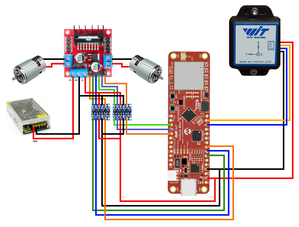
Because this project is considered as a proof of concept and for learning purposes, fast prototyping DuPont jumpers were used for the connections between the AVR 128DB48 IoT board, the H-Bridge and the WT901C-TTL sensor.
Each module was connected independently with the AVR128DB48 IoT board and tested with the corresponding code before integrating a complete device. In the following sections, we describe this.
WT901C SensorThe WT901C 9-axis digital module incorporates a 3-axis accelerometer, 3-axis gyroscope, and 3-axis magnetic field sensors. It integrates a Kalman dynamic filtering algorithm for solving the current real-time motion posture of the module and has a 200Hz rate.
The WT901C sends data thru a UART, allowing for serial communication with the AVR 128DB48. The Serial2 port was used in this board. The transmitting line (TX) of the sensor is attached to the receiving line (RX) of the AVR 128DB48 board. Same for the RX line, attached to the TX line in the micro controller board (crossed connections).
A PC program was used for the first test of the WT901C sensor, together with a USB to serial TTL cable. This allowed to obtain the 9-axis data, display it and graph.
For fast prototyping and using the WT901C sensor, a Software Development Kit (SDK) is provided. This is quite useful, as it implements the interaction of the sensor with different micro-controllers, programming languages and applications.
The first program for testing the WT901C sensor and obtaining the data, employ the Serial2 instruction as we are using the USART2 on the AVR 128DB48 board. For some reason, this didn't work, so we had to turn to the software serial implementation.
The dual H-Bridge motor driver based on the L298 integrated circuit is very convenient for driving two DC motors with PWM signals. It incorporates two control lines for each motor, allowing for full stop or change of direction, according to the following table:
It is important to note that the AVR 128DB48 IoT is a 3.3V device and the H-Bridge motor driver expects input signals at 5V. For this reason, a pair of voltage shifters were used. The H-Bridge motor driver has a pair of jumpers that, when placed, send full voltage to the motors. When removed, PWM signals can be applied for adjusting the motors speeds. This bridge also incorporates a 5V regulator that was used for feeding the voltage shifters.
PWM signals are generated by using the analogWrite instruction. A test program was developed derived from the gpio.ino example, in which the switch 0 is detected via interrupts. In our case, we increase the duty cycle for the PWM signal with each press.
The complete code for both test programs can be found in the attachments to this project.
IoT ImplementationFurther analysis of the vibration data will be done in Matlab. For this reason, we are programming the code for sending the vibration data to the ThingSpeak web site. AT-commands are being investigated for implementing this functionality with the AVR 128DB48 IoT board.


_3u05Tpwasz.png?auto=compress%2Cformat&w=40&h=40&fit=fillmax&bg=fff&dpr=2)
Comments