

A MAGNETIC LEVITATION project with no special but only standard components – including a modified cheap standard relay as the electromagnet – powered with only 5V@50mA from a USB-Powerbank
A floating object is always a fascinating eye-catcher, which I like to place on my desk. Many conversations at this table had a nice smalltalk beginning with it.So in the last years I have recreated some „magnetic levitation“ projects from various publications.
But I was never really satisfied with the results.: Too big, too unstable, gigantic power consumption(;-), the flight stability was not very good and especially the necessary electromagnet always had to be somehow winded around a screw by myself. The results were often not very nice to look at, but above all hardly reproducible.
So I had gained a lot of experience and a mechanical construction and a simple electrical circuit was created, which proved itself in all test setups:
Here you can see a video of the final setup: https://vimeo.com/430336526
Some Impressions:
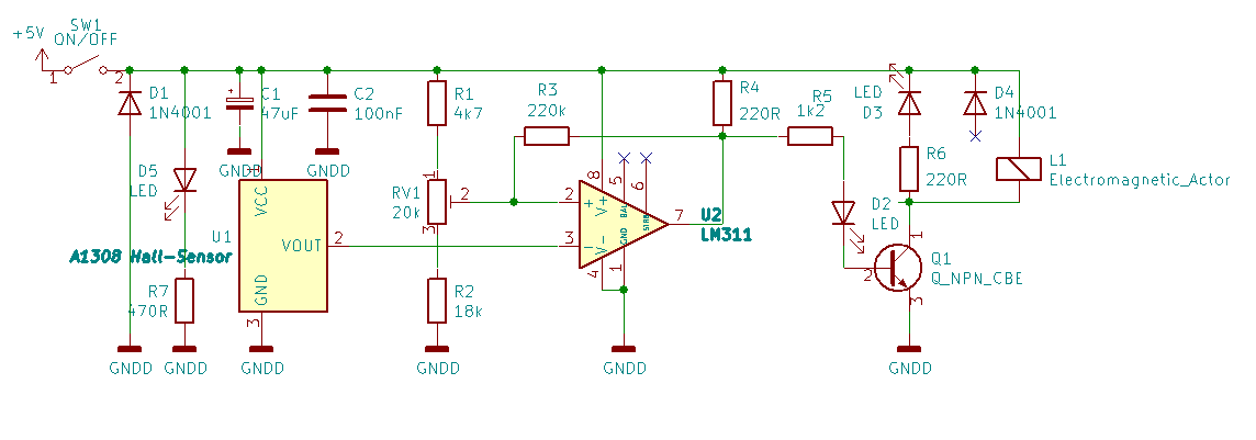
The schematic:
# The HALL magnetic sensor used is an A1302 or its successor A1308 – the cheaper and widely used 49S or similar types are NOT suitable.
# The necessary comparator is a LM311
# The magnetic coil is a cheap modified 5V standard relay (tested: HW-482 /JQC-3FF-S-Z or JQC3F-05VDC) with built-in switching transistor from the world of microcontroller actuators. The coil starts anti-clockwise at the PLUS-contact.
The relay has a U-shaped iron core. That core has to be changed to a J-shape by shortening the part that holds the middle-contact of the relais. Thus now only one magnetic pole points towards the „payload“
The next pictures show the steps of modification regarding the relay:
- Remove the screw-contacts.
- Carefully remove the relais housing with a cutter starting at the corners.
- Remove the movable relais middle-contact and shorten the upper static contact.
- Cut off the magnetic counter pole and rest of the movable contact with a dremel or a metal saw,
- position the Hall sensor with its flat side on the coil core,
- connect the three contacts of the Hall sensor to the rests of the three old relay contacts.
The three relay-contacts are modified to connect the three pins of the A1302/A1308 HALL-sensor to the PCB:
- HALL-Vcc-pin1>> relais-NO;
- Hall-GND-pin2>>relais-NC;
- Hall-Vout-pin3>>Relay-MiddleContact
# Two neodymium permanent magnets in disc form with 10mm (or 12mm) diameter and 2mm (or 3mm) height are used to make a LEGO man, a screw or a table tennis ball (with extra payload of a screw) float. VOut of U1 increases if the magnet comes near – if it decreases turn the magnets around!!! Same behavior if the electromagnet is switched on – else twist the two contacts of the coil!
# The power supply should not be very expensive. In the end it works very well with only 5V and only about 50mA. So a very simple USB power bank can be used as power supply – and can also be used as a safe stand.# As a positioning aid, the relay’s original flyback diode has been replaced by a white LED with 220R series resistor – this LED only lights up when the object is at the right height and hovers. I found two good positions for this LED: Next to the Hall-sensor (= a bit tricky) or pointing from the side towards the magnets (= easy)
# An opaque plastic shield protects the HALL-Sensor against shortcut and mecanical stress.
# A PC slot bracket is used to keep the electromagnet at the correct height of about 8cm above the power bank without vibration. The downside end of the plate gets angled and glued to the power bank with double-sided mounting tape.
The HALL sensor measures the sum of the magnetic field strength of the permanent magnet and the electromagnet. As the magnets approach, the voltage increases at VOut of the HALL sensor. The comparator U1 compares this voltage with the adjustable voltage (RV1) and switches off the electromagnet if the field strength becomes too high.The permanent magnets including the LEGO man’s load „hang“ at the point where their own weight corresponds exactly to the force with which the magnets and the iron core of the coil attract each other. This force is first increased by the electromagnet when it is switched on. However, as soon as the Hall sensor measures a magnetic field that is too strong, the electromagnet switches off and the object falls briefly until the Hall sensor again measures a magnetic field that is too weak and the electromagnet briefly lifts the object again. There is a hysteresis created by R3, which influences the created minimal puls width.At this floating point the magnet switches at about 300 to 400 times per second. The induction voltage generated when the electromagnet is switched off is no more only limited by the build in diode but now it causes diode D6 to light up precisely and only at the floating point.For adjustment, this floating point must be found. To do this, place a stack of small Post-It sheets about 15mm thick between the magnet and the coil core. The number of sheets is now chosen so that the magnet just begins to be pulled up only a little bit when the stack of paper is in between.Hold this position and adjust RV1 so that there is a voltage of 0 mV between pin2 and pin3 of U1 and LED D2 just gets dark.Then the floating object is brought to this point without a stack of paper and RV1 is readjusted a little bit until the object „hangs“ and D6 lights up.
I modified three 5V-relais and at all my three test-circuits I had to adjust a voltage of 3.45V +-50mV between GRND and U1/Pin2 without a near magnet.
This procedure of calibration is a bit tricky and depends especially on the weight of the „payload“ – don’t give up!!
I had a lot of fun with this and hope this description will make it easy for someone else to build such a „levitation project“.
Good luck!

Comments