


Hardware components | ||||||
 |
| × | 1 | |||
 |
| × | 1 | |||
| × | 1 | ||||
 |
| × | 1 | |||
| × | 1 | ||||
| × | 1 | ||||
Hand tools and fabrication machines | ||||||
| ||||||
 |
| |||||
Hi! Here is my infinity mirror, powered by the NXP FRDM-K82F board and Neopixels.
Instead of just publishing the whole project, I will try to separate the project in different parts; that is the way I learned and made this project, and hopefully it will help you too.
The parts:- NXP FRDM-K82F - Understanding the board and useful links to help
- Controlling LEDs - the Buildin and external through GPIO
- Accelerometer - What is it, and how to get the data
- Compass - Let's rotate the project
- Temperature sensor - How to get the temperature data
- Connecting the Neopixel - Lighting up the lights
- The fun code parts - light effects, sounds and other stuff
- Bluetooth communication - a start to make it accessible through a phone
The main hardware:
- NXP FRDM-K82F
- Neopixel / WS2812 RGB LED strip with 60 LEDs for the inner circle, 65 LEDs for the outer circle (125 total)
- J-LINK edu debug programmer from Segger
Included are the following sample projects
- GPIO, timing, delays and LEDs
- Controlling one neopixel
- Controlling multiple Neopixels in different colors
There are a few tutorials, guidelines and information pages I used to get knowledge of the NXP FRDM-K82F board. Click on the hyperlinks below to go to those sources;
Take your time to read the sources above; it really helps you to understand the board, software, SDK and hardware schematics.
I use the Kinetics SDK (v3.2.0) with the 2.0 SDK.
Please note that it could be possible that you have to update the bootloader of the FRDM K82F when you receive it before it is possible to upload a program to it. Download the OpenSDA2.1 firmware from Segger. Unplug the power cable, press and hold the reset-button (SW1) and plugin the power cable. On your computer a folder named Bootloader appears and copy the OpenSDA firmware-file in this folder. The board will reboot and you're up and running.
If you are using Windows 10, it can give some problems, there is now a betaversion of OpenSDA2.2 that should fix it, but I haven't tried that one yet.
To connect the NXP board and connect it with our PC I refer to the official NXP Getting Started documentation [link]. I use the Segger J-Link debugger for programming the board. The J-Link is connected to the J19 port; please note that you connect it in the right direction. It costed me a few hours of debugging to find out that I connected the J-Link in the opposite way..
Now it's a good time to watch the webinar trainings if you haven't seen them already:
Now we can start, so say Hello to the K82F;
printf("Hello K82F");
The RGB LED has a shared Pin for the input. Those Pins are: PTC8 (red), PTC9 (green), PTC10 (blue).
in the pin_mux.c add the following GPIO changes;
PORT_SetPinMux(PORTC, 8U,  kPORT_MuxAsGpio); // red
PORT_SetPinMux(PORTC, 9U,  kPORT_MuxAsGpio); // green
PORT_SetPinMux(PORTC, 10U, kPORT_MuxAsGpio); // blue
The following code is in main.c
Make a delay function, which is needed to show the different colors of the RGB LED;
void delay_s(uint16_t t) {
	volatile uint32_t i = 0;
	volatile uint32_t delay_t = 8000000 * t; // decrease to 8000 for a ms delay
	for (i = 0; i < delay_t; ++i) {
		__asm("NOP");
	}
mark the GPIO as output:
gpio_pin_config_t pin_config = {kGPIO_DigitalOutput, 1};
Connect both;
	GPIO_PinInit(GPIOC, 8U,  &pin_config);
	GPIO_PinInit(GPIOC, 9U,  &pin_config);
	GPIO_PinInit(GPIOC, 10U, &pin_config);
And write the data to the LEDs and call for the delay;
	for(;;)
	{
		GPIO_WritePinOutput(GPIOC, 8u, 0);
		delay_s(1);
		GPIO_WritePinOutput(GPIOC, 8u, 1);
		GPIO_WritePinOutput(GPIOC, 9u, 0);
		delay_s(1);
		GPIO_WritePinOutput(GPIOC, 9u, 1);
		GPIO_WritePinOutput(GPIOC, 10u, 0);
		delay_s(1);
		GPIO_WritePinOutput(GPIOC, 10u, 1);
	}
Now build the project (right mouse on the projects folder in the Project Explorer and click Build Project). and then Debug it by clicking on the bug in the toolbar. let it build and see the build-in RGB change color every second.
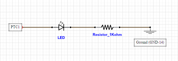
Controlling an external LED through the GPIO pins is almost the same as controlling the build-in RGB LED, only now you have to connect the physical LED and make sure that the GPIO is connected to an available pin.
Connect a resistor and LED to the board. Like this:
Create a new project.
in pin_mux.c
// Set the PTC1 port as GPIO (GPIO C pin 1) on the J4 I/O header.
PORT_SetPinMux(PORTC, 1u, kPORT_MuxAsGpio);
In main.c
// Set the struct pin_config to output. (the 1 is for output make it 0 for input)
gpio_pin_config_t pin_config = {kGPIO_DigitalOutput, 1};
// Connect the set GPIO pin to the set GPIO 'output' functionality
GPIO_PinInit(GPIOC, 1U, &pin_config);
// Turn the output on (high) or off (low)
GPIO_WritePinOutput(GPIOC, 1u, High) // turn the LED on
GPIO_WritePinOutput(GPIOC, 1u, Low)  // turn the LED off
Code project sample: I made a simple/sample project named "Tutorial_LEDs" which contains a project file for the FRDM K82F that include the above sample which controls the RGB LED, timers and GPIO on the board. The project is available in the code section below.
The out-of-the-box firmware that is loaded on the FRDM-K82F is a good example to start with; use the build-in accelerometer to control the build in RGB led. The following codes and examples are snippets of the official Demo Applications from the FRDM K82F, named the Bubble project. The accelerometer is connected internally by I2C, which means it will share the output pins
- PTA1 (ACCEL_I2C_SDA)
- PTA2 (ACCEL_I2C_SCL)
- PTC13 (ACCEL_INT1)
The accelerometer uses the I2C 0x1C address, which is the default address of the sensor.
// Get new accelerometer data;
FXOS_ReadSensorData(&fxosHandle, &sensorData);
// Get the X and Y data from the sensor data structure.fxos_data
xData = (int16_t)((uint16_t)((uint16_t)sensorData.accelXMSB << 8) |                                                (uint16_t)sensorData.accelXLSB);
yData = (int16_t)((uint16_t)((uint16_t)sensorData.accelYMSB << 8) |                                                (uint16_t)sensorData.accelYLSB);
For explanation about the FlexIO I reffer to the following links and blog posts:
The CompassI make use of the FRDM K82F sample application to determine how to read the buildin Compass data. The sample project 'ecompass_frdmk82f' shows the functionality of the compass. Load it and debug it on the board; first a calibration is needed to determined what the north is; press a key and rotate the board around. If the board is calibrated the output on Putty gives the "jaw" data of the compass.
The Compass is internally connected by I2C; since the magnetometer is on the same chip as the accelerometer, the I2C address is 0x1C.
NeopixelsIn total there are 125 (awesome) neopixels (WS2812B) RGB LEDs in this project; 60 in the inner circle and 65 in the outer circle.
Neopixels require specific timing. It took me a little while to understand it and make it to work. I have to say; I don't (yet) use the FlexIO nor the specific SPI protocols, but I've got them working by making data packets send through a GPIO port with specific timing. This is not the most optimal method, but I got the Clock functionality working with it.
To power the Neopixels I use an external power supply; a Micro-USB through a breakout module. Make always sure that if you use an external power supply to share the ground of the external power supply and the FRDM K82F board!
The neopixels can handle the GPIOs ouput power of 3.3V, but since the Neopixels are build for a datasignal of 5V, I used a 74LS245 in a circuit to create a 5V data signal out of the 3V datasignal of the K82F.
Setup
int totalLEDs= 125; // amount of total Neopixels
The following function will collect the data packages and send them to the LEDs, timing is included in this function.
void SendNeopixelData(GPIO_Type *base, uint32_t pin, uint32_t *data, int length) { ...
With the following functions of the parameters;
GPIO_Type *base  the GPIO header, in my case GPIOC
uint32_t pin     The pin number of which the Neopixels are connected to
uint32_t *data   a pointer to a data array which contains the Color data for each LED
int length       The amount of packages in data
Data packets
void SendNeopixelData(GPIO_Type *base, uint32_t pin, uint32_t *data, int length)
{
int bitcount;
uint32_t dataWord;
uint32_t pinMask = 1U << pin;
while (length > 0)
{
    bitcount = 23;
    dataWord = *data;
    while (bitcount>0)
    {
    if (dataWord & 0x0800000U) {


        DELAY_100nS;
        DELAY_100nS;

	DELAY_100nS;
	DELAY_100nS;
	base->PCOR = pinMask;
	DELAY_100nS;
	DELAY_100nS;
    } else {
	base->PSOR = pinMask;
	DELAY_100nS;
	DELAY_100nS;
	DELAY_100nS;
	DELAY_100nS;
	DELAY_10nS;
	DELAY_10nS;
	DELAY_10nS;
	base->PCOR = pinMask;
	DELAY_100nS;
	DELAY_100nS;
	DELAY_100nS;
	DELAY_100nS;
	DELAY_100nS;
	DELAY_100nS;
	DELAY_100nS;
    }
bitcount--;
dataWord = dataWord <<1;
}
// last bit has a different timing
if (dataWord & 0x0800000U) {
    base->PSOR = pinMask;
        DELAY_100nS;
        DELAY_100nS;
        DELAY_100nS;
        DELAY_100nS;
        DELAY_100nS;
        DELAY_100nS;
        DELAY_100nS;
        DELAY_100nS;
        DELAY_100nS;
        base->PCOR = pinMask;
        DELAY_10nS;
	DELAY_10nS;
	DELAY_10nS;
	DELAY_10nS;
	DELAY_10nS;
    }
    else {
	base->PSOR = pinMask;
	DELAY_100nS;
	DELAY_100nS;
	DELAY_100nS;
	DELAY_100nS;
	DELAY_10nS;
	DELAY_10nS;
	DELAY_10nS;
	base->PCOR = pinMask;
	DELAY_100nS;
	DELAY_100nS;
	DELAY_100nS;
	DELAY_100nS;
	DELAY_100nS;
    }
    data++;
    length--;
}
}
Each Package is an uint32_t, name 'data' in this example. For each led a package
Note that a the color from the WS2812b is not send in the format Red - Green Blue (RGB), but they are send in the following order: Green Red Blue (GRB)
Useful sites and more information about the Neopixels can be found here:
Real Time ClockI use the DS1307 [datasheet] module for the Real Time Clock (RTC) which include a cell battery.
Sorry for not including the source code available since I couldn't make it to work as I would liked to be.
connect an external temperature sensor, in my case the DS1621 temperature sensor. This sensor is connected by I2C, whereby the SCL and SDA pins needs to be connected to the PTA1 and PTA2. The DS1621 uses the 0x48 as default I2C address, but can be assigned between 0x48 - 0x4F through the three address pins (A0, A1 and A2) on the chip. If you don't have an temperature sensor, a function called DummyTemperature(int temp) is available in the code section below which will just send a temperature sensor to the Temperature_LED_config(int temp) function.
LEDstrip functions: Fpositive temperature: The temperature (in Celsius) will be shown in the amount of LEDs, if the temperature is below zero, the color will be blue.
// The temperature parameter will be the amount of LEDs to light up.
// If the temperature is above zero, the color will be green, for below zero the
// color will be blue and if the temperature is zero the color is red.
void Temperature_LED_config(int temp)
{
	uint32_t temp_plus_color = 0xFF0000; // green
	uint32_t temp_min_color  = 0x0000FF; // blue
	uint32_t temp_norm_color = 0x222222; // white
	uint32_t temp_zero_color = 0x005500; // red
	uint32_t data[totalLEDs];
	int i = outerCircleLEDs; // start point after the outerCircle
	temp = temp + i;
	while(i < totalLEDs)
	{
		if(temp > 0)
		{
			if(i < temp)
			{
				data[i] = temp_plus_color;
			}
			else
			{
				data[i] = temp_norm_color;
			}
		}
		if(temp < 0)
		{
			if(i < temp)
			{
				data[i] = temp_min_color;
			}
			else
			{
				data[i] = temp_norm_color;
			}
		}
		if(temp == 0)
		{
			data[i] = temp_zero_color;
		}
		i++;
	}
   SendNeopixelData(GPIO_LED, PIN_LED, data, totalLEDs);
}
Bluetooth is always a fun in a project; wireless controlling a board by a self made application is great! Only making it work takes me a lot of time. I've some experiences in the Windows development, but I couldn't yet make sending data work. I was be able to create a simple Windows 10 application for my phone (Lumia 930) whereby the Bluetooth connection can be made with the HC-05 Bluetooth module connected on the J24 header on the FRDM K82F. I'm still working on this functionality, but here is a sneak peak of the application:
During the European Maker Week (30 may - 5 June 2016) I had the opportunity to create the housing and case for this project at the FabLab in Breda, the Netherlands. They are specialized in 3D printing, Laser cutting and designing housings, objects and a lot of other cool things. It was a really nice experience! And I personally love the result.
Creating the Infinity effect
By putting the lights between two mirrors, the light bounces between the mirrors. To see through one of the mirrors make it possible to see a tunnel effect as created in this project. To make a see-through mirror, I stick the one-way mirror foil on a transparent perspex plate. The one-way foil has a transparency of 85%.
So the different layers of the mirror are (from bottom to top)
- A transparent plate / glass / perspex
- The one-way mirror foil
- a housing that includes he LEDs
- A normal mirror
Be patient when placing the foil on the transparent plate, since it is easy to let air bubbles between the foil and the plate. Tips I can give is to clean the plate with alcohol, and make it wet with a few drups of water and a little bit of dish soap (like 1 drop with 1 liter of water).
Besides the normal stuff that is used for making a project like this, the parts below I had to get for making this project;
- The FRDM K82F board I got from hackster.io, but would normally cost around 50$ USD
- Segger J-LINK EDU ~75$ USD (Via Mouser.com, electronics webshop)
- WS2812b (~2m) for ~30$ USD (Via Ebay)
- DS1306 temperature sensor ~2$ USD (via online electronics webshop)
- 74LS245 - Circuit to make a stable 5V output ~7$ USD (local electronics shop)
- One-way mirror foil; ~15$ USD (via Ebay)
- Mirror, transparent perspex-plate, glue, wooden housing: ~30$ USD (Via Local hardware store)
Many thanks to the websites, people and projects for help and learn me to make this project;
FabLabBreda - for helping and creating the housing of the mirror [link]
James Stephanic - for explaining the J-link debug programmer here at the Hackster.io comment section of his project. [link]
Erich Styger - for explaining the Neopixels and FlexIO on his website. He as a lot of tutorials and complex projects detailed on his website for the FRDM K82f and other Freescale development boards. [link]
NXP - for making the FRDM-K82F board for the Hackster.io challenge available, quick reply's for support and advanced answers to my questions.
Hackster.io - for being an amazing community that makes projects as this one happen.
You - for reading this project, (and for ignoring my English grammar ;). I learned a lot by writing my first project and hopefully it will help you make amazing things!
This is my first written project so tips, suggestions and feedback/feedforward is always welcome :)
Good luck with your project and have a nice day.


Comments